Instant Connection for Pixel Streaming
— New Feature Automated Setup

Blender for 3D Printing: Advanced Model Preparation
DigitalArt
-
Blender for 3D Printing: Advanced Model Preparation
DigitalArt
Blender for 3D Printing: Advanced Model Preparation
DigitalArt
-
Table of Contents
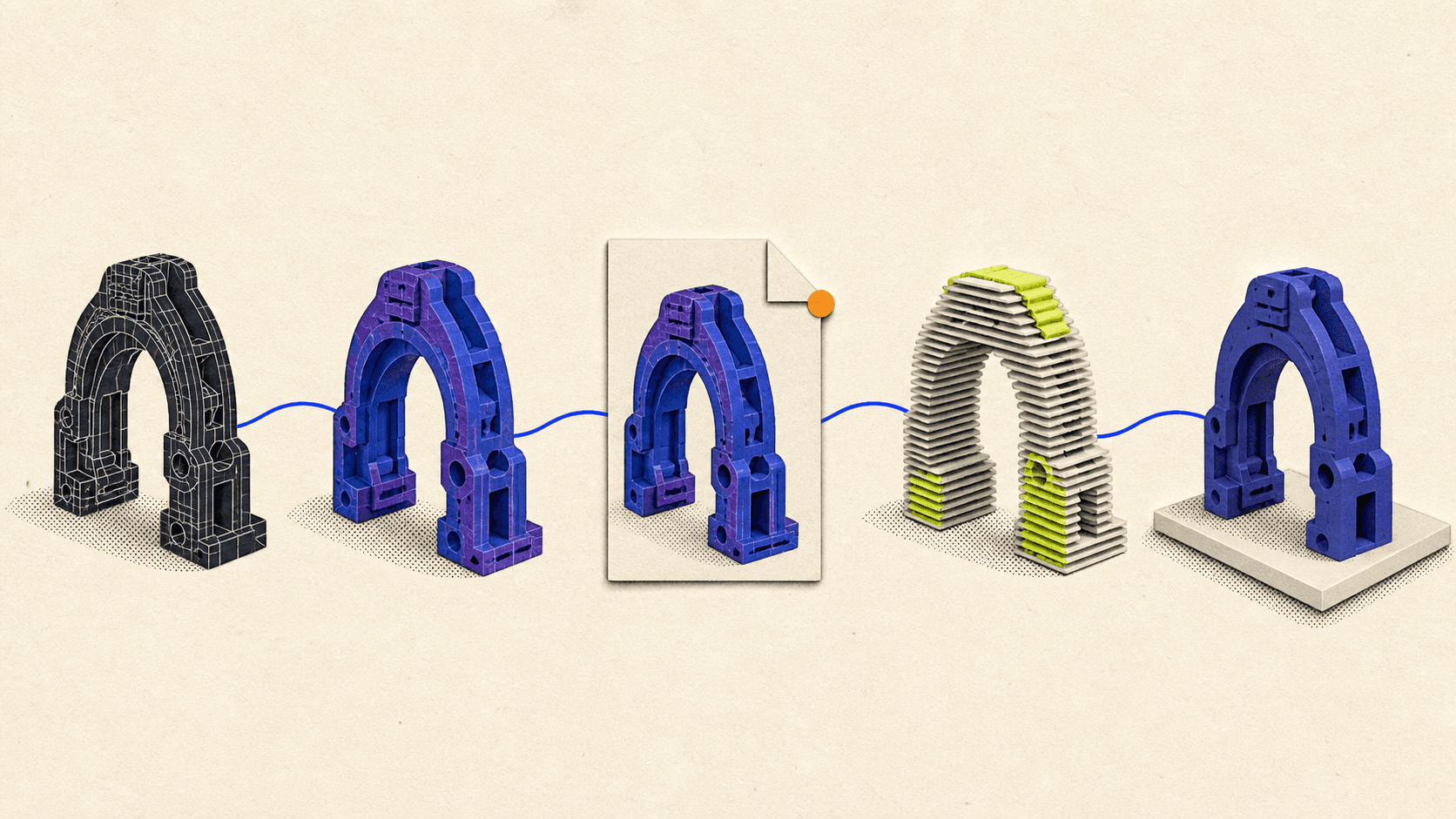
Blender can create and prepare printable models, but a successful workflow does not end at export. You must confirm real-world scale, produce an unambiguous solid mesh, account for the intended printing process, export the geometry, and inspect the sliced layers before sending anything to a printer.
That distinction matters. Blender prepares the model, while a slicer converts the exported geometry into printer-specific layers and instructions. For most FDM printers, those instructions are G-code. Resin printers often use a machine-specific sliced file instead.
A model can look flawless in Blender and still fail at either stage. Open edges, flipped normals, internal faces, insufficient wall thickness, overlapping shells, or an incorrect unit assumption may only become visible after slicing.
This workflow uses the current Blender 5.2 LTS interface and the current 3D Print Toolbox extension, which supports Blender 4.2 and newer.
Is Blender Good For 3D Printing?
Blender is well suited to creating organic models, sculptures, figurines, props, enclosures, and other polygon-based objects for 3D printing. It provides precise dimensions, Boolean modeling, remeshing, mesh cleanup, normals tools, modifiers, and STL import and export.
Its main limitation is that Blender is a polygonal modeling application rather than a parametric manufacturing system. You can work accurately, but dimensions and relationships do not automatically remain constrained after every edit. If a hole must stay at an exact diameter or two components require a controlled fit, you need to keep checking those measurements.
Blender also does not know the complete manufacturing context. A mesh contains the shape, but printability also depends on:
The FDM or resin printing process
The specific printer
Nozzle or optical resolution
Layer height
Filament or resin behavior
Part orientation
Supports
Slicer settings
Printer calibration
The practical boundary is simple: use Blender for modeling, geometry repair, scale, and mesh validation. Use the slicer for printer profiles, material settings, orientation refinement, supports, layers, toolpaths, and printer output.
Before editing the mesh, make a print-preparation copy of the object. Keep the original model and modifier stack intact so you can return to it if a Boolean, remesh, or automated repair changes more geometry than expected.
Set Up Real-World Scale And Dimensions
Scale problems are especially common in STL workflows because STL describes triangles without providing dependable unit metadata. A coordinate value may be interpreted as millimeters by one application even if it represented meters somewhere else.
That makes scale a three-stage check: verify it in Blender, control it during export, and verify it again in the slicer.
Confirm the print method and physical requirements
Decide whether the part is intended for FDM or resin printing before finalizing the geometry. Also identify:
Required finished dimensions
Printer build volume
Likely print orientation
Functional or decorative purpose
Surfaces that need the best finish
Components that must fit together
Material-dependent shrinkage or warping concerns
Orientation can change support placement, layer-direction strength, surface quality, tolerances, and drainage. It should influence the design rather than being treated as a last-minute slicer decision.
Set Blender’s units
Open Scene Properties and choose a real-world Unit System, normally Metric for a millimeter-based printing workflow. Set the Length display that makes the model easiest to inspect.
Blender’s Unit Scale setting primarily controls conversion and display in the interface. It does not make every operation behave as if the scene were physically resized.
Select the object and open the Item panel in the 3D Viewport. Enter or inspect the final X, Y, and Z dimensions numerically. Do not rely on the apparent size of the grid.
Apply rotation and scale
An object can have the correct visible dimensions while retaining non-uniform object scale. This matters because modifiers and other geometry operations may depend on local object coordinates.
For example, the Solidify modifier calculates thickness using local coordinates. Non-uniform scale can therefore create different physical wall thicknesses on different sides of an object.
In Object Mode, use Object > Apply > Rotation & Scale or Ctrl+A, then confirm that the Scale values are 1.0. Applying transforms preserves the visible shape while transferring the transform into the object data, as explained in the Blender Apply documentation.
Recheck the object’s dimensions immediately afterward.
Make The Mesh Watertight And Manifold
A printable solid needs a surface that clearly separates an inside volume from the outside world. This is often described as watertight or manifold geometry.
In plain language, a watertight model has no unintended openings. A manifold surface also has an unambiguous structure. On a typical closed shell, every surface edge belongs to exactly two faces. An edge attached to one face forms an open boundary, while an edge attached to three or more faces creates an ambiguous junction.
The Blender non-manifold problem can include:
Holes and open boundaries
Loose vertices or edges
Edges connected to more than two faces
Faces with no thickness
Interior faces
Disconnected fragments
Shells touching only at a vertex
Geometry that folds through itself
Watertight and manifold are related, but they are not interchangeable with “printable.” A closed shell can still contain self-intersections, trapped surfaces, or features that are too thin for the printer.

Clean loose, duplicate, and degenerate geometry
Enter Edit Mode and inspect the complete mesh.
Use Mesh > Clean Up > Delete Loose to remove selected vertices, edges, or faces that are not connected to the intended surface. Loose geometry may be invisible in a solid viewport but still confuse analysis or slicing.
Use Merge by Distance to join duplicate vertices that should occupy the same point. Keep the merge threshold conservative. An aggressive value can collapse narrow gaps, small holes, or deliberate detail.
Degenerate geometry includes zero-length edges and faces with effectively no area. Blender’s mesh cleanup tools can remove or collapse these elements, but the result still needs visual inspection.
Resolve intersections and internal faces
Two objects can overlap visually without forming one clean solid. Some slicers interpret overlapping shells successfully, but results vary, especially when the overlap creates coplanar faces or contradictory internal regions.
If separate pieces are meant to become one physical body, use a Boolean Union and inspect the evaluated result. Remove obsolete internal surfaces rather than leaving them trapped inside the part.
Do not automatically union objects that are meant to remain separate, move independently, or receive different materials. Each printable component should instead be a valid closed solid with the required clearance from neighboring parts.
Use section views, X-ray mode, or temporary hiding to look inside the model. Internal faces are easy to miss because they do not affect the visible exterior.
Repair open and non-manifold regions
In Edit Mode, use Select > Select All by Trait > Non-Manifold to locate suspicious boundaries and junctions.
The correct repair depends on the cause:
Fill a genuine hole with appropriate topology.
Remove a redundant internal face.
Join vertices that should meet.
Separate shells that should not share a point.
Rebuild an area where several surfaces meet ambiguously.
Delete tiny disconnected fragments.
Use a Boolean or remesh when intersecting shells should become one volume.
The 3D Print Toolbox also includes a Make Manifold operation. Treat it as an assisted repair, not a guarantee. Automated repair may fill an opening you intended to preserve or alter a detailed region. Compare the repaired object with the original before continuing.
Check Normals, Thickness, Intersections, And Detail
Once the shell is structurally closed, inspect the properties that determine how the surface will be interpreted and manufactured.
Correct normals and face orientation
A face normal is a vector indicating which direction a polygon considers its outside. Inconsistent normals can confuse inside-outside calculations and cause parts of the model to be interpreted incorrectly.
Enable Viewport Overlays > Face Orientation. Outward-facing regions normally appear blue, while back-facing regions appear red when viewed from outside.
In Edit Mode, select the relevant faces and use Mesh > Normals > Recalculate Outside, or Shift+N. Recalculate Inside is available for intentionally inward-facing surfaces.
Recalculation is not a general mesh repair command. It can correct orientation across connected geometry, but it does not close holes, remove internal faces, or resolve intersections. Review the result with the Face Orientation overlay instead of assuming the operation worked everywhere.
A hollow model needs a consistent outer surface and a consistently oriented inner surface. Random red patches on the exterior usually indicate a problem, while an inner wall will naturally face the cavity.
Confirm wall thickness and printable detail
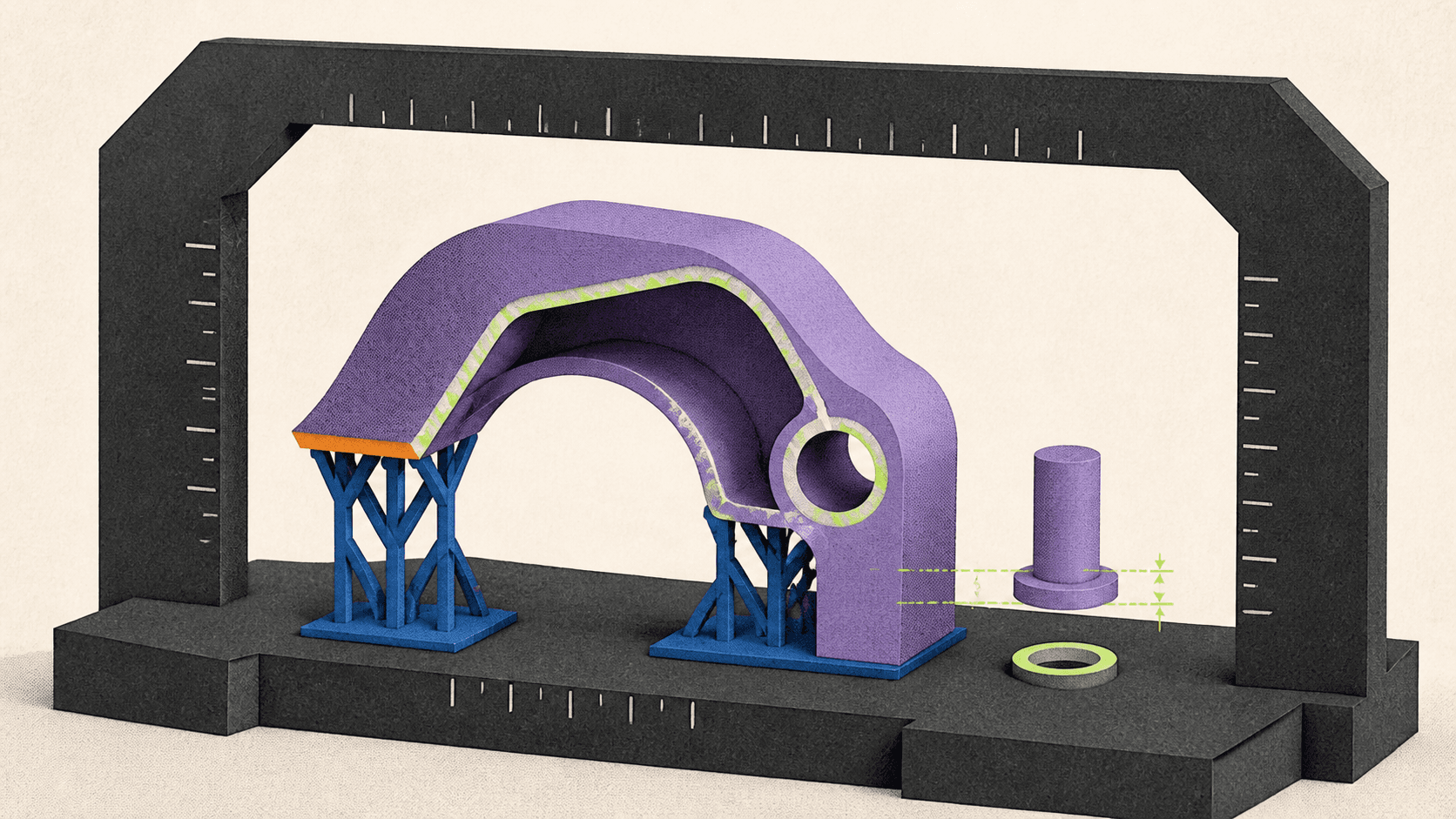
Every printed surface needs physical volume. A single plane may render correctly from both sides, but it has zero real thickness and does not define a printable solid.
The Solidify modifier can add depth to a surface. Apply object scale before judging its thickness, and inspect sharp corners where the generated walls may intersect or become thinner than expected. Blender’s even-thickness options improve many cases but cannot guarantee perfect thickness for every topology.
There is no universal minimum wall thickness. For FDM, printable walls depend partly on nozzle size, extrusion width, layer settings, material, cooling, and the slicer’s thin-wall strategy. A wall narrower than a usable extrusion path may disappear or be modified during slicing.
For resin, the limits depend on the printer’s optical system, resin, exposure profile, orientation, support strategy, and whether the wall is supported. A value from one printer or resin guide should not be presented as a general rule.
Check more than the main walls:
Pins and narrow columns
Raised lettering
Engraved text
Grooves
Small holes
Knife edges
Thin decorative elements
Contact points between larger forms
Smooth shading does not create additional printable detail. A low-sided cylinder may look round in the viewport but export as a visibly faceted mesh. Inspect the actual wireframe and add only enough resolution to represent the shape at the intended print size.
Excessive subdivision has its own cost. Although the Subdivision Surface modifier can produce smoother geometry, unnecessary subdivision increases file size and makes Boolean operations, remeshing, validation, and slicer processing heavier without improving detail beyond the printer’s capability.
Design clearances for the actual process
Two parts modeled with zero clearance will not reliably slide, rotate, or snap together after printing.
Required clearance depends on:
Printer calibration
Material shrinkage and warping
Part size
Horizontal or vertical orientation
Surface geometry
Fit type
Layer height
Slicer compensation
Post-processing
As Prusa’s modeling guidance notes, there is no single universal tolerance. A loose hinge, a sliding assembly, a press fit, and a glued alignment pin all need different design allowances.
For an unfamiliar printer-material combination, use a small clearance or fit test before committing to a large model. That is especially important for moving assemblies and resin parts that will change slightly during washing or post-curing.
Prepare The Model For FDM Or Resin Printing
The common mesh requirements remain the same for both processes: correct scale, closed solids, consistent normals, sufficient thickness, and intentional clearances. Orientation and support decisions differ considerably.
Preparing for FDM
FDM printers build objects by depositing material in successive paths. Each new region needs support from the previous layer, a printable bridge, or generated support material.
Evaluate the model for:
Steep overhangs
Long bridges
Features beginning in mid-air
Small contact areas on the build plate
Support trapped in inaccessible cavities
Critical surfaces positioned above supports
Structural loads crossing weak layer bonds
Do not rely on one universal overhang angle. Cooling, nozzle, material, layer height, speed, and printer design all change what can be printed cleanly. Use the slicer’s overhang analysis with the actual printer profile.
Orientation affects strength because FDM parts are direction-dependent. A component loaded across layer bonds may behave differently from the same geometry printed in another orientation.
Sometimes the best solution is to split a model into several parts. Each part can then receive a more suitable orientation, cleaner support placement, or stronger layer direction. Add alignment features and appropriate clearance if the pieces will be assembled later.

Preparing for resin
Resin printing also builds in layers, but the process introduces different orientation and support concerns. Unsupported islands, large cross-sections, suction cups, trapped resin, and support marks can all affect the result.
Hollowing can reduce material use and cross-sectional mass, but it also creates an internal cavity that must be designed for printing, drainage, washing, and curing. Hollowing is not automatically appropriate for every part.
For a hollow resin model:
Choose the likely print orientation first.
Add drainage and venting that work in that orientation.
Avoid enclosed pockets that trap liquid resin.
Check for cup-shaped regions that create suction.
Ensure internal areas can be cleaned.
Avoid internal supports that cannot be removed when removal is required.
Formlabs’ orientation guidance recommends inspecting the model layer by layer for unsupported minima and suction risks. Drain-hole size and wall recommendations must come from the printer and resin manufacturer’s current design guide, not from a generic Blender value.
For both FDM and resin, decide where support marks are acceptable. Rotate detailed or presentation surfaces away from dense support contact when possible.
Export STL And Move To A Slicer
Export is a handoff between two different stages. Blender sends surface geometry; the slicer combines that geometry with manufacturing settings.
Validate the final mesh
Install the current 3D Print Toolbox from Edit > Preferences > Get Extensions. Search for 3D Print Toolbox, install it, and open its panel in the 3D Viewport sidebar.
Use it to inspect the final object for bad geometry, volume, scale, and other print-related issues. The exact checks available can change between extension versions, so use the current interface rather than following an old Blender 3.x screenshot.
Also inspect the evaluated modifier result. A base mesh can be clean while a Boolean, Solidify, Mirror, Remesh, or displacement operation introduces intersections or open regions.
If modifiers are being preserved non-destructively, duplicate the object before applying them. Validate the same geometry you intend to export.
Export the STL deliberately
If you are looking for the Blender export STL step, use File > Export > STL and review the options instead of accepting them blindly.
The current Blender STL exporter includes controls for:
Selection Only
Export scale
Scene Unit
Axis conversion
Applying modifiers
Binary or ASCII output
Select only the print-ready object and enable Selection Only so cameras, reference meshes, hidden prototypes, or unrelated scene objects are not exported accidentally.
Enable Apply Modifiers when the final evaluated modifier result is meant to become the printable mesh. Confirm that viewport and render visibility settings produce the intended result.
Binary STL is normally more compact than ASCII STL. ASCII is useful mainly when another tool or workflow specifically requires human-readable output.
A Blender STL file contains triangulated surface geometry. It does not preserve the Blender modifier stack, materials, textures, lighting, object hierarchy, support settings, slicer profile, or reliable real-world unit declaration.
A Blender STL import can also be useful as a verification step. Import the exported file into a clean Blender scene, check its dimensions, and inspect the geometry without relying on the original modifier stack.

Pre-Export Checklist
Before leaving Blender, confirm that:
The intended print process and orientation have been considered.
Final dimensions are correct.
Rotation and scale are applied where appropriate.
Every printable surface has physical thickness.
There are no unintended holes or boundary edges.
There are no loose vertices, loose edges, or tiny fragments.
Duplicate vertices have been resolved without collapsing detail.
Intersecting shells have been handled intentionally.
Internal faces and unwanted internal shells are removed.
Exterior normals face outward.
Wall thickness and detail suit the target printer and material.
Functional parts include process-appropriate clearance.
The final evaluated modifier result has been inspected.
Only the intended objects will be exported.
Scene Unit and export scale are set deliberately.
Import the model into a slicer
Open the exported STL in the slicer used for the target printer. Immediately compare its X, Y, and Z dimensions with the Blender dimensions.
If the size is wrong, determine why before scaling it casually in the slicer. Otherwise, you may hide a repeatable unit error and produce inconsistent future exports.
Select the actual printer, nozzle or resin, material, and layer profile. Then configure the process-specific settings.
For FDM, these may include:
Orientation
Layer height
Perimeters
Top and bottom layers
Infill
Supports
Bed adhesion
Bridge and overhang behavior
For resin, they may include:
Orientation
Layer settings
Supports and contact points
Hollowing
Drain holes
Island detection
Printer-specific exposure or material profiles
These settings belong in the slicer because they depend on the machine and manufacturing process, not only on the shape.
Slice and preview every layer
The phrase “Blender STL to G-code” describes a two-application workflow, not a direct Blender conversion. Blender exports the STL, then an FDM slicer turns it into layer-by-layer toolpaths and G-code.
For resin printing, the slicer performs the same conceptual role but may export a proprietary printer job rather than standard G-code.
After slicing, inspect the complete layer preview. Look for:
Walls that disappear
Holes that close
Separate shells that merge unexpectedly
Empty or unintended internal regions
Unsupported islands
Toolpaths starting in mid-air
Inaccessible support structures
Discontinuous perimeters
Unexpected solid regions
Resin cups or trapped cavities
Dimensions changed by slicer compensation
The sliced preview is more informative than the solid model view because it shows what the printer has actually been instructed to build.

Fix Common Blender 3D Printing Problems
When a model fails, diagnose the symptom at the correct stage. For crashes, viewport slowdowns, and other issues outside the printing workflow, see these common Blender problems and solutions.
Symptom | Likely Cause | First Check |
|---|---|---|
Model arrives extremely small or large | STL unit assumption or export scale | Compare Blender and slicer dimensions |
Part of the model disappears | Zero-thickness or unprintably thin geometry | Inspect sliced perimeters layer by layer |
Slicer closes an intentional opening | Non-manifold or ambiguous surface | Check boundary edges, normals, and internal faces |
Unexpected cavities appear | Intersecting shells or trapped geometry | Inspect the model with section views |
Exterior faces appear missing | Reversed or inconsistent normals | Enable Face Orientation |
Round surfaces look polygonal | Insufficient actual mesh resolution | Inspect the wireframe rather than smooth shading |
Separate components fuse | Insufficient clearance | Review the fit allowance and slicer compensation |
Boolean result contains artifacts | Coplanar faces, self-intersections, or poor input topology | Inspect and simplify the Boolean operands |
FDM surface above support is rough | Orientation or support-interface limitation | Reorient, split, or move supports |
Hollow resin model fails | Island, suction cup, or drainage problem | Review every layer in the resin slicer |
Dimensions remain inaccurate | Scale, calibration, material behavior, or compensation | Separate digital scale errors from physical process errors |
Avoid repairing every issue with remeshing. Remesh can create a unified surface, but it may soften edges, close small holes, erase detail, or change dimensions. Use it when its tradeoffs suit the model, and compare the result against the original.
Likewise, a slicer’s automatic repair should be treated as a diagnostic convenience. If it changes the model, return to Blender and understand the underlying geometry before relying on that repair for a critical part.
When A Cloud Computer Helps With Blender
Most basic print preparation does not require unusual hardware. The situation changes with dense scans, high-resolution sculpts, complex Boolean assemblies, large Remesh operations, heavy modifier stacks, or scenes containing many detailed parts.
These workloads can exhaust the memory or processing capacity of a lightweight laptop. The viewport may become difficult to navigate, and geometry checks or modifier evaluations may take longer as mesh density increases.
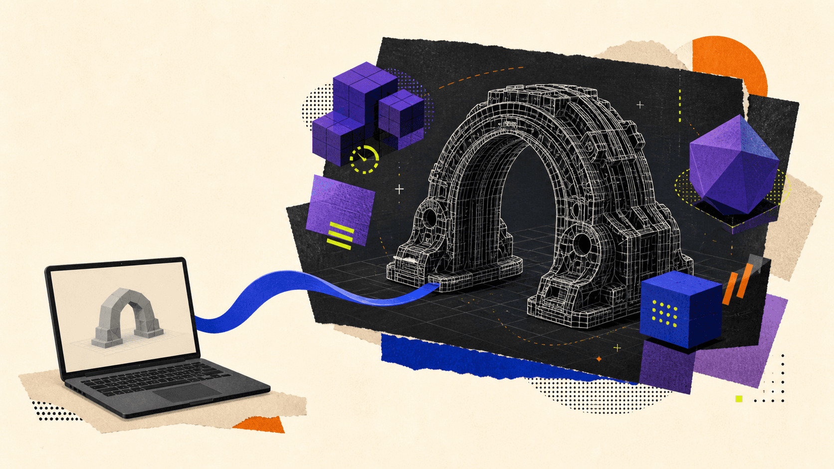
Vagon Cloud Computer provides remote access to a configurable cloud workstation where you can install and run Blender. This can help when you need more CPU, memory, or GPU capacity for a demanding preparation session, or when you need the full Blender interface from a device that cannot run the project comfortably on its own.
It does not replace the slicer, material profile, printer calibration, physical printer connection, or layer-preview check. More compute makes heavy geometry easier to work with, but it does not make an invalid mesh printable.
A practical approach is to keep routine modeling local and use a cloud workstation when the final high-poly Boolean, remesh, validation, or export pass exceeds the local machine’s comfortable limits. Account for connection quality, project-transfer time, session usage, and persistent storage when deciding whether that workflow fits the project.
If you want to see how the remote workflow works in practice, this guide explains how to use Blender on a cloud computer, including setup, file transfer, and performance selection.
A reliable Blender for 3D printing workflow is ultimately a chain of verification: define the manufacturing constraints, establish scale, build a clear solid, validate the actual geometry, export it deliberately, and inspect what the slicer will send to the printer. If complex assets are making that process difficult on your current hardware, try Vagon Cloud Computer for the Blender stages that need more power.
Blender can create and prepare printable models, but a successful workflow does not end at export. You must confirm real-world scale, produce an unambiguous solid mesh, account for the intended printing process, export the geometry, and inspect the sliced layers before sending anything to a printer.
That distinction matters. Blender prepares the model, while a slicer converts the exported geometry into printer-specific layers and instructions. For most FDM printers, those instructions are G-code. Resin printers often use a machine-specific sliced file instead.
A model can look flawless in Blender and still fail at either stage. Open edges, flipped normals, internal faces, insufficient wall thickness, overlapping shells, or an incorrect unit assumption may only become visible after slicing.
This workflow uses the current Blender 5.2 LTS interface and the current 3D Print Toolbox extension, which supports Blender 4.2 and newer.
Is Blender Good For 3D Printing?
Blender is well suited to creating organic models, sculptures, figurines, props, enclosures, and other polygon-based objects for 3D printing. It provides precise dimensions, Boolean modeling, remeshing, mesh cleanup, normals tools, modifiers, and STL import and export.
Its main limitation is that Blender is a polygonal modeling application rather than a parametric manufacturing system. You can work accurately, but dimensions and relationships do not automatically remain constrained after every edit. If a hole must stay at an exact diameter or two components require a controlled fit, you need to keep checking those measurements.
Blender also does not know the complete manufacturing context. A mesh contains the shape, but printability also depends on:
The FDM or resin printing process
The specific printer
Nozzle or optical resolution
Layer height
Filament or resin behavior
Part orientation
Supports
Slicer settings
Printer calibration
The practical boundary is simple: use Blender for modeling, geometry repair, scale, and mesh validation. Use the slicer for printer profiles, material settings, orientation refinement, supports, layers, toolpaths, and printer output.
Before editing the mesh, make a print-preparation copy of the object. Keep the original model and modifier stack intact so you can return to it if a Boolean, remesh, or automated repair changes more geometry than expected.
Set Up Real-World Scale And Dimensions
Scale problems are especially common in STL workflows because STL describes triangles without providing dependable unit metadata. A coordinate value may be interpreted as millimeters by one application even if it represented meters somewhere else.
That makes scale a three-stage check: verify it in Blender, control it during export, and verify it again in the slicer.
Confirm the print method and physical requirements
Decide whether the part is intended for FDM or resin printing before finalizing the geometry. Also identify:
Required finished dimensions
Printer build volume
Likely print orientation
Functional or decorative purpose
Surfaces that need the best finish
Components that must fit together
Material-dependent shrinkage or warping concerns
Orientation can change support placement, layer-direction strength, surface quality, tolerances, and drainage. It should influence the design rather than being treated as a last-minute slicer decision.
Set Blender’s units
Open Scene Properties and choose a real-world Unit System, normally Metric for a millimeter-based printing workflow. Set the Length display that makes the model easiest to inspect.
Blender’s Unit Scale setting primarily controls conversion and display in the interface. It does not make every operation behave as if the scene were physically resized.
Select the object and open the Item panel in the 3D Viewport. Enter or inspect the final X, Y, and Z dimensions numerically. Do not rely on the apparent size of the grid.
Apply rotation and scale
An object can have the correct visible dimensions while retaining non-uniform object scale. This matters because modifiers and other geometry operations may depend on local object coordinates.
For example, the Solidify modifier calculates thickness using local coordinates. Non-uniform scale can therefore create different physical wall thicknesses on different sides of an object.
In Object Mode, use Object > Apply > Rotation & Scale or Ctrl+A, then confirm that the Scale values are 1.0. Applying transforms preserves the visible shape while transferring the transform into the object data, as explained in the Blender Apply documentation.
Recheck the object’s dimensions immediately afterward.
Make The Mesh Watertight And Manifold
A printable solid needs a surface that clearly separates an inside volume from the outside world. This is often described as watertight or manifold geometry.
In plain language, a watertight model has no unintended openings. A manifold surface also has an unambiguous structure. On a typical closed shell, every surface edge belongs to exactly two faces. An edge attached to one face forms an open boundary, while an edge attached to three or more faces creates an ambiguous junction.
The Blender non-manifold problem can include:
Holes and open boundaries
Loose vertices or edges
Edges connected to more than two faces
Faces with no thickness
Interior faces
Disconnected fragments
Shells touching only at a vertex
Geometry that folds through itself
Watertight and manifold are related, but they are not interchangeable with “printable.” A closed shell can still contain self-intersections, trapped surfaces, or features that are too thin for the printer.
Clean loose, duplicate, and degenerate geometry
Enter Edit Mode and inspect the complete mesh.
Use Mesh > Clean Up > Delete Loose to remove selected vertices, edges, or faces that are not connected to the intended surface. Loose geometry may be invisible in a solid viewport but still confuse analysis or slicing.
Use Merge by Distance to join duplicate vertices that should occupy the same point. Keep the merge threshold conservative. An aggressive value can collapse narrow gaps, small holes, or deliberate detail.
Degenerate geometry includes zero-length edges and faces with effectively no area. Blender’s mesh cleanup tools can remove or collapse these elements, but the result still needs visual inspection.
Resolve intersections and internal faces
Two objects can overlap visually without forming one clean solid. Some slicers interpret overlapping shells successfully, but results vary, especially when the overlap creates coplanar faces or contradictory internal regions.
If separate pieces are meant to become one physical body, use a Boolean Union and inspect the evaluated result. Remove obsolete internal surfaces rather than leaving them trapped inside the part.
Do not automatically union objects that are meant to remain separate, move independently, or receive different materials. Each printable component should instead be a valid closed solid with the required clearance from neighboring parts.
Use section views, X-ray mode, or temporary hiding to look inside the model. Internal faces are easy to miss because they do not affect the visible exterior.
Repair open and non-manifold regions
In Edit Mode, use Select > Select All by Trait > Non-Manifold to locate suspicious boundaries and junctions.
The correct repair depends on the cause:
Fill a genuine hole with appropriate topology.
Remove a redundant internal face.
Join vertices that should meet.
Separate shells that should not share a point.
Rebuild an area where several surfaces meet ambiguously.
Delete tiny disconnected fragments.
Use a Boolean or remesh when intersecting shells should become one volume.
The 3D Print Toolbox also includes a Make Manifold operation. Treat it as an assisted repair, not a guarantee. Automated repair may fill an opening you intended to preserve or alter a detailed region. Compare the repaired object with the original before continuing.
Check Normals, Thickness, Intersections, And Detail
Once the shell is structurally closed, inspect the properties that determine how the surface will be interpreted and manufactured.
Correct normals and face orientation
A face normal is a vector indicating which direction a polygon considers its outside. Inconsistent normals can confuse inside-outside calculations and cause parts of the model to be interpreted incorrectly.
Enable Viewport Overlays > Face Orientation. Outward-facing regions normally appear blue, while back-facing regions appear red when viewed from outside.
In Edit Mode, select the relevant faces and use Mesh > Normals > Recalculate Outside, or Shift+N. Recalculate Inside is available for intentionally inward-facing surfaces.
Recalculation is not a general mesh repair command. It can correct orientation across connected geometry, but it does not close holes, remove internal faces, or resolve intersections. Review the result with the Face Orientation overlay instead of assuming the operation worked everywhere.
A hollow model needs a consistent outer surface and a consistently oriented inner surface. Random red patches on the exterior usually indicate a problem, while an inner wall will naturally face the cavity.
Confirm wall thickness and printable detail
Every printed surface needs physical volume. A single plane may render correctly from both sides, but it has zero real thickness and does not define a printable solid.
The Solidify modifier can add depth to a surface. Apply object scale before judging its thickness, and inspect sharp corners where the generated walls may intersect or become thinner than expected. Blender’s even-thickness options improve many cases but cannot guarantee perfect thickness for every topology.
There is no universal minimum wall thickness. For FDM, printable walls depend partly on nozzle size, extrusion width, layer settings, material, cooling, and the slicer’s thin-wall strategy. A wall narrower than a usable extrusion path may disappear or be modified during slicing.
For resin, the limits depend on the printer’s optical system, resin, exposure profile, orientation, support strategy, and whether the wall is supported. A value from one printer or resin guide should not be presented as a general rule.
Check more than the main walls:
Pins and narrow columns
Raised lettering
Engraved text
Grooves
Small holes
Knife edges
Thin decorative elements
Contact points between larger forms
Smooth shading does not create additional printable detail. A low-sided cylinder may look round in the viewport but export as a visibly faceted mesh. Inspect the actual wireframe and add only enough resolution to represent the shape at the intended print size.
Excessive subdivision has its own cost. Although the Subdivision Surface modifier can produce smoother geometry, unnecessary subdivision increases file size and makes Boolean operations, remeshing, validation, and slicer processing heavier without improving detail beyond the printer’s capability.
Design clearances for the actual process
Two parts modeled with zero clearance will not reliably slide, rotate, or snap together after printing.
Required clearance depends on:
Printer calibration
Material shrinkage and warping
Part size
Horizontal or vertical orientation
Surface geometry
Fit type
Layer height
Slicer compensation
Post-processing
As Prusa’s modeling guidance notes, there is no single universal tolerance. A loose hinge, a sliding assembly, a press fit, and a glued alignment pin all need different design allowances.
For an unfamiliar printer-material combination, use a small clearance or fit test before committing to a large model. That is especially important for moving assemblies and resin parts that will change slightly during washing or post-curing.
Prepare The Model For FDM Or Resin Printing
The common mesh requirements remain the same for both processes: correct scale, closed solids, consistent normals, sufficient thickness, and intentional clearances. Orientation and support decisions differ considerably.
Preparing for FDM
FDM printers build objects by depositing material in successive paths. Each new region needs support from the previous layer, a printable bridge, or generated support material.
Evaluate the model for:
Steep overhangs
Long bridges
Features beginning in mid-air
Small contact areas on the build plate
Support trapped in inaccessible cavities
Critical surfaces positioned above supports
Structural loads crossing weak layer bonds
Do not rely on one universal overhang angle. Cooling, nozzle, material, layer height, speed, and printer design all change what can be printed cleanly. Use the slicer’s overhang analysis with the actual printer profile.
Orientation affects strength because FDM parts are direction-dependent. A component loaded across layer bonds may behave differently from the same geometry printed in another orientation.
Sometimes the best solution is to split a model into several parts. Each part can then receive a more suitable orientation, cleaner support placement, or stronger layer direction. Add alignment features and appropriate clearance if the pieces will be assembled later.
Preparing for resin
Resin printing also builds in layers, but the process introduces different orientation and support concerns. Unsupported islands, large cross-sections, suction cups, trapped resin, and support marks can all affect the result.
Hollowing can reduce material use and cross-sectional mass, but it also creates an internal cavity that must be designed for printing, drainage, washing, and curing. Hollowing is not automatically appropriate for every part.
For a hollow resin model:
Choose the likely print orientation first.
Add drainage and venting that work in that orientation.
Avoid enclosed pockets that trap liquid resin.
Check for cup-shaped regions that create suction.
Ensure internal areas can be cleaned.
Avoid internal supports that cannot be removed when removal is required.
Formlabs’ orientation guidance recommends inspecting the model layer by layer for unsupported minima and suction risks. Drain-hole size and wall recommendations must come from the printer and resin manufacturer’s current design guide, not from a generic Blender value.
For both FDM and resin, decide where support marks are acceptable. Rotate detailed or presentation surfaces away from dense support contact when possible.
Export STL And Move To A Slicer
Export is a handoff between two different stages. Blender sends surface geometry; the slicer combines that geometry with manufacturing settings.
Validate the final mesh
Install the current 3D Print Toolbox from Edit > Preferences > Get Extensions. Search for 3D Print Toolbox, install it, and open its panel in the 3D Viewport sidebar.
Use it to inspect the final object for bad geometry, volume, scale, and other print-related issues. The exact checks available can change between extension versions, so use the current interface rather than following an old Blender 3.x screenshot.
Also inspect the evaluated modifier result. A base mesh can be clean while a Boolean, Solidify, Mirror, Remesh, or displacement operation introduces intersections or open regions.
If modifiers are being preserved non-destructively, duplicate the object before applying them. Validate the same geometry you intend to export.
Export the STL deliberately
If you are looking for the Blender export STL step, use File > Export > STL and review the options instead of accepting them blindly.
The current Blender STL exporter includes controls for:
Selection Only
Export scale
Scene Unit
Axis conversion
Applying modifiers
Binary or ASCII output
Select only the print-ready object and enable Selection Only so cameras, reference meshes, hidden prototypes, or unrelated scene objects are not exported accidentally.
Enable Apply Modifiers when the final evaluated modifier result is meant to become the printable mesh. Confirm that viewport and render visibility settings produce the intended result.
Binary STL is normally more compact than ASCII STL. ASCII is useful mainly when another tool or workflow specifically requires human-readable output.
A Blender STL file contains triangulated surface geometry. It does not preserve the Blender modifier stack, materials, textures, lighting, object hierarchy, support settings, slicer profile, or reliable real-world unit declaration.
A Blender STL import can also be useful as a verification step. Import the exported file into a clean Blender scene, check its dimensions, and inspect the geometry without relying on the original modifier stack.
Pre-Export Checklist
Before leaving Blender, confirm that:
The intended print process and orientation have been considered.
Final dimensions are correct.
Rotation and scale are applied where appropriate.
Every printable surface has physical thickness.
There are no unintended holes or boundary edges.
There are no loose vertices, loose edges, or tiny fragments.
Duplicate vertices have been resolved without collapsing detail.
Intersecting shells have been handled intentionally.
Internal faces and unwanted internal shells are removed.
Exterior normals face outward.
Wall thickness and detail suit the target printer and material.
Functional parts include process-appropriate clearance.
The final evaluated modifier result has been inspected.
Only the intended objects will be exported.
Scene Unit and export scale are set deliberately.
Import the model into a slicer
Open the exported STL in the slicer used for the target printer. Immediately compare its X, Y, and Z dimensions with the Blender dimensions.
If the size is wrong, determine why before scaling it casually in the slicer. Otherwise, you may hide a repeatable unit error and produce inconsistent future exports.
Select the actual printer, nozzle or resin, material, and layer profile. Then configure the process-specific settings.
For FDM, these may include:
Orientation
Layer height
Perimeters
Top and bottom layers
Infill
Supports
Bed adhesion
Bridge and overhang behavior
For resin, they may include:
Orientation
Layer settings
Supports and contact points
Hollowing
Drain holes
Island detection
Printer-specific exposure or material profiles
These settings belong in the slicer because they depend on the machine and manufacturing process, not only on the shape.
Slice and preview every layer
The phrase “Blender STL to G-code” describes a two-application workflow, not a direct Blender conversion. Blender exports the STL, then an FDM slicer turns it into layer-by-layer toolpaths and G-code.
For resin printing, the slicer performs the same conceptual role but may export a proprietary printer job rather than standard G-code.
After slicing, inspect the complete layer preview. Look for:
Walls that disappear
Holes that close
Separate shells that merge unexpectedly
Empty or unintended internal regions
Unsupported islands
Toolpaths starting in mid-air
Inaccessible support structures
Discontinuous perimeters
Unexpected solid regions
Resin cups or trapped cavities
Dimensions changed by slicer compensation
The sliced preview is more informative than the solid model view because it shows what the printer has actually been instructed to build.
Fix Common Blender 3D Printing Problems
When a model fails, diagnose the symptom at the correct stage. For crashes, viewport slowdowns, and other issues outside the printing workflow, see these common Blender problems and solutions.
Symptom | Likely Cause | First Check |
|---|---|---|
Model arrives extremely small or large | STL unit assumption or export scale | Compare Blender and slicer dimensions |
Part of the model disappears | Zero-thickness or unprintably thin geometry | Inspect sliced perimeters layer by layer |
Slicer closes an intentional opening | Non-manifold or ambiguous surface | Check boundary edges, normals, and internal faces |
Unexpected cavities appear | Intersecting shells or trapped geometry | Inspect the model with section views |
Exterior faces appear missing | Reversed or inconsistent normals | Enable Face Orientation |
Round surfaces look polygonal | Insufficient actual mesh resolution | Inspect the wireframe rather than smooth shading |
Separate components fuse | Insufficient clearance | Review the fit allowance and slicer compensation |
Boolean result contains artifacts | Coplanar faces, self-intersections, or poor input topology | Inspect and simplify the Boolean operands |
FDM surface above support is rough | Orientation or support-interface limitation | Reorient, split, or move supports |
Hollow resin model fails | Island, suction cup, or drainage problem | Review every layer in the resin slicer |
Dimensions remain inaccurate | Scale, calibration, material behavior, or compensation | Separate digital scale errors from physical process errors |
Avoid repairing every issue with remeshing. Remesh can create a unified surface, but it may soften edges, close small holes, erase detail, or change dimensions. Use it when its tradeoffs suit the model, and compare the result against the original.
Likewise, a slicer’s automatic repair should be treated as a diagnostic convenience. If it changes the model, return to Blender and understand the underlying geometry before relying on that repair for a critical part.
When A Cloud Computer Helps With Blender
Most basic print preparation does not require unusual hardware. The situation changes with dense scans, high-resolution sculpts, complex Boolean assemblies, large Remesh operations, heavy modifier stacks, or scenes containing many detailed parts.
These workloads can exhaust the memory or processing capacity of a lightweight laptop. The viewport may become difficult to navigate, and geometry checks or modifier evaluations may take longer as mesh density increases.
Vagon Cloud Computer provides remote access to a configurable cloud workstation where you can install and run Blender. This can help when you need more CPU, memory, or GPU capacity for a demanding preparation session, or when you need the full Blender interface from a device that cannot run the project comfortably on its own.
It does not replace the slicer, material profile, printer calibration, physical printer connection, or layer-preview check. More compute makes heavy geometry easier to work with, but it does not make an invalid mesh printable.
A practical approach is to keep routine modeling local and use a cloud workstation when the final high-poly Boolean, remesh, validation, or export pass exceeds the local machine’s comfortable limits. Account for connection quality, project-transfer time, session usage, and persistent storage when deciding whether that workflow fits the project.
If you want to see how the remote workflow works in practice, this guide explains how to use Blender on a cloud computer, including setup, file transfer, and performance selection.
A reliable Blender for 3D printing workflow is ultimately a chain of verification: define the manufacturing constraints, establish scale, build a clear solid, validate the actual geometry, export it deliberately, and inspect what the slicer will send to the printer. If complex assets are making that process difficult on your current hardware, try Vagon Cloud Computer for the Blender stages that need more power.
Get Beyond Your Computer Performance
Run applications on your cloud computer with the latest generation hardware. No more crashes or lags.

Trial includes 1 hour usage + 7 days of storage.
Summarize with AI
Ready to focus on your creativity?
Vagon gives you the ability to create & render projects, collaborate, and stream applications with the power of the best hardware.

Vagon Blog
Run heavy applications on any device with
your personal computer on the cloud.
San Francisco, California
Solutions
Vagon Teams
Vagon Streams
Use Cases
Resources
Vagon Blog
How to Use DaVinci Resolve With Codex: MCP & Computer Use
How to Use ComfyUI With Claude: MCP & Computer Use Guide
How to Use Rhino With Codex: MCP & Computer Use Guide
How to Use KiCad With Codex: MCP & Computer Use Guide
How to Use KiCad With Claude: MCP & Computer Use Guide Meta
How to Use FreeCAD With Codex: MCP & Computer Use
How to Use FreeCAD With Claude: MCP & Computer Use
How to Use 3ds Max With Codex: MCP & Computer Use
How to Use Houdini With Claude: MCP & Computer Use
Vagon Blog
Run heavy applications on any device with
your personal computer on the cloud.
San Francisco, California
Solutions
Vagon Teams
Vagon Streams
Use Cases
Resources
Vagon Blog
How to Use DaVinci Resolve With Codex: MCP & Computer Use
How to Use ComfyUI With Claude: MCP & Computer Use Guide
How to Use Rhino With Codex: MCP & Computer Use Guide
How to Use KiCad With Codex: MCP & Computer Use Guide
How to Use KiCad With Claude: MCP & Computer Use Guide Meta
How to Use FreeCAD With Codex: MCP & Computer Use
How to Use FreeCAD With Claude: MCP & Computer Use
How to Use 3ds Max With Codex: MCP & Computer Use
How to Use Houdini With Claude: MCP & Computer Use
Vagon Blog
Run heavy applications on any device with
your personal computer on the cloud.
San Francisco, California
Solutions
Vagon Teams
Vagon Streams
Use Cases
Resources
Vagon Blog