Instant Connection for Pixel Streaming
— New Feature Automated Setup

How to Use KiCad With Codex: MCP & Computer Use Guide
Architecture
-
How to Use KiCad With Codex: MCP & Computer Use Guide
Architecture
How to Use KiCad With Codex: MCP & Computer Use Guide
Architecture
-
Table of Contents
Your prototype works, but testing the next batch is harder than it should be. The reset signal is buried beside the microcontroller, the supply rail has no convenient probe point, and the assembly folder contains files from two different revisions. Before ordering Rev B, you need more than a cleaner-looking layout. You need a controlled change and a reliable record of what changed.
Using Codex with KiCad can help connect those tasks. A compatible MCP server gives Codex access to structured project information and supported design operations. Depending on the connector, those operations may modify saved files or communicate with a running editor. Computer Use provides a separate route for navigating KiCad’s interface and inspecting details that need visual context.
Neither connection is a native KiCad feature, and neither guarantees a working circuit. Your connector, KiCad version, desktop environment, and permissions determine what Codex can actually do.
This guide follows an existing microcontroller board from Rev A to Rev B. The goal is to add approved debug access, inspect the result, compare rule-check findings, and prepare a consistent release package without rebuilding unrelated parts of the design.

Source: KiCad Documentation Contributors
Start With a Revision Brief, Not an Open-Ended Design Prompt
For this board, Rev B should improve debug access without redesigning the circuit. Tell Codex which nets need access, why you need it, and which physical constraints must remain unchanged. “Add useful test points” is too broad: Codex would have to guess what you intend to measure and how you will reach it.
Specify the approved nets by their actual project names. Include the probe or fixture requirements where known. A handheld probe, oscilloscope probe, and pogo-pin fixture have different placement needs.
A short revision brief makes the boundary explicit:
Requirement | Acceptance condition |
|---|---|
Debug access | Test points connect only to approved nets |
Mechanical layout | Board outline, mounting holes, and fixed connectors remain unchanged |
Existing circuitry | No unrelated component or net changes |
Identification | Each new test point has an agreed reference and readable label |
Verification | Changes are reviewed against the saved Rev A baseline |
Adding a test point is not electrically neutral in every design. Extra copper, branches, and probe loading can affect sensitive signals. Begin with user-selected low-speed or supply measurement points, and require engineering review before modifying high-speed, RF, or precision analog paths.
Give Codex the brief before enabling writes:
Inspect the project and propose a Rev B plan for the approved debug nets. Do not modify files. Identify what must remain unchanged, suggest test point options, and list the information you need before proceeding.
The first deliverable should be a scoped proposal with unresolved questions, not an edited PCB.
Give Codex Two Different Paths Into KiCad
MCP and Computer Use solve different access problems. The first exposes tools and project data; the second lets Codex inspect and operate the graphical interface. Configure and test them independently so you know which route a task uses.
Connect a file-oriented MCP server
For this walkthrough, KiCad Copilot provides a documented Codex connection. Its requirements include Node.js 20 or newer, KiCad 9 or 10, and Python 3 for component conversion and analysis features.
After reviewing the third-party package, register it with Codex:
The first command configures a local STDIO server launched through npx. It can download and execute the package, so treat it as installing software, not merely adding a bookmark. Record the package version used, and consider a reviewed, pinned version for a repeatable setup.
Codex stores server settings in its MCP configuration. Restart the client after registration, then confirm that the server connects and exposes its tools. A configured entry in codex mcp list is not proof that a project operation succeeds.
Start with an inspection request:
Inspect the project at the supplied absolute path. Report its schematic and PCB files, the discovered KiCad CLI version, and the approved debug nets you can identify. Do not modify, synchronize, or export anything.
Compare the response with your project. If kicad-cli is installed somewhere unusual, the connector supports an explicit KICAD_CLI_PATH setting.
This server edits saved files, not the live editor buffer. Before a write, save intentional KiCad changes. Afterward, reload or reopen the affected document carefully. Do not save an older editor buffer over the updated file. Other connectors may use IPC, but their live-access requirements should not be applied to this setup.
Enable Computer Use separately
In a supported desktop environment, install or enable the Computer Use plugin and review its app access settings. On macOS, grant the required Screen Recording and Accessibility permissions yourself. On Windows, keep KiCad visible in the active desktop session.
Windows Computer Use takes foreground control, so avoid simultaneous mouse or keyboard input during the task. Codex CLI access alone does not provide these desktop capabilities.
For the first screen test, ask Codex to locate the open PCB and report its filename without editing anything. Approve KiCad access when prompted, and stop if it selects the wrong window.
Only proceed when both tests identify the same project. File access and screen access must agree before they can support one revision workflow.
Build a Baseline Codex Can Compare Against
Before adding anything, preserve Rev A as a known starting point. A recoverable project copy or Git commit should include the schematic hierarchy, PCB, project settings, and relevant local libraries. Keep existing manufacturing files separately identified so they cannot be mistaken for the future Rev B outputs.
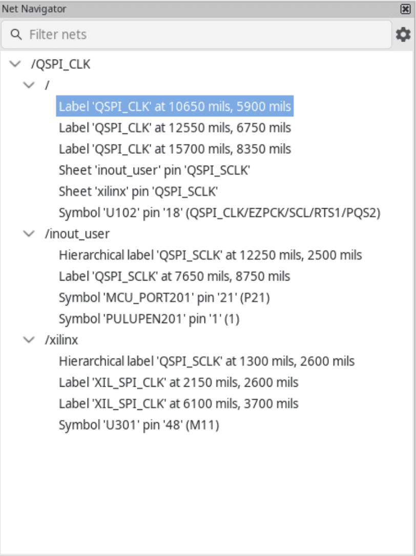
The baseline needs more than a screenshot. Ask Codex to record the exact project path, KiCad version, sheet structure, and the net connections relevant to your revision. In a hierarchical design, similarly named labels can have different scopes. Confirm the intended connection through the project’s connectivity data rather than matching text alone.
Source: KiCad Documentation Contributors
Capture the objects that matter
For each approved debug net, identify the connected component references and pins, existing access points, and corresponding PCB pads. Also record the fixed objects protected by your revision brief.
A compact baseline might contain:
Baseline item | Purpose |
|---|---|
Approved net and connected pins | Establish the intended electrical connection |
Existing test points or connector access | Avoid unnecessary additions |
Fixed footprint positions and rotations | Detect unintended movement |
Board outline and mounting holes | Preserve mechanical constraints |
ERC and DRC reports | Separate existing findings from new ones |
Existing access is worth checking first. A suitable connector pin or exposed pad may already meet your measurement needs, making another test point unnecessary.
Request a read-only summary:
Build a Rev A baseline for the approved debug nets. List their connected pins, existing access points, and relevant PCB pads. Record protected footprint positions and identify unresolved net-name or hierarchy questions. Do not change the project.
Keep analysis separate from approval
File-based tools such as kicad-happy can support structured review, but their findings still need interpretation. Missing operating conditions, incomplete models, or unsupported cases can limit the analysis. Do not convert a suggested issue directly into an authorized edit.
Run baseline ERC and DRC using the settings you intend to retain for the comparison. Save the reports with the revision record.
Finally, preserve both machine-readable data and a short human-readable summary. A text diff can reveal changed objects, but it does not explain whether a test point is accessible or a new branch is appropriate. Those questions need the design brief and later visual review.
Add Debug Access Without Rebuilding the Board
With the Rev A baseline preserved, turn the approved net list into specific additions. Each test point needs a schematic reference, a verified connection, and a footprint appropriate for the intended probe. Do not let Codex invent library identifiers or choose pad dimensions without considering your measurement setup.
For illustration, suppose the revision brief approves access to RESET_N and +3V3. These are example names, not nets Codex should assume exist in your project. It must resolve the actual connections before proposing changes.
Add the schematic connection first
Ask Codex to find suitable symbols and footprints in the available libraries, then present their identifiers and relevant dimensions. Decide whether you need a bare probe pad, a loop-style component, or a fixture contact. Those choices affect mechanical access and assembly requirements.

Source: KiCad Documentation Contributors
Approve the schematic edit only after reviewing the proposed mapping:
Add the approved test point symbols to the specified sheet and connect each to its confirmed net. Use the agreed references and footprint assignments. Preserve existing components and connections. Stop if the operation requires broader changes, and report the resulting connectivity before updating the PCB.
After the edit, verify that each symbol pin belongs to the intended net. A nearby label or a wire that looks connected is insufficient evidence.
Next, explicitly synchronize the schematic changes with the board. KiCad’s forward annotation transfers design information, but it does not decide where a new footprint should sit or complete its routing. Review synchronization changes for unexpected replacements, removals, or altered net assignments.

Source: KiCad Documentation Contributors
Approve a local placement, not a fresh layout
For each new footprint, specify the intended board side and an acceptable placement region. Consider probe approach, nearby component height, access after assembly, and a suitable ground reference for the measurement.
There is an important connector-specific detail: KiCad Copilot’s documented placement workflow can apply a returned PCB even when producing a preview. A preview filename therefore does not establish that the operation is read-only.
Generate candidates on a disposable project copy unless you have verified the operation’s preservation behavior. If the tool cannot retain existing placement and routing, do not use a full-board layout operation for this small revision. Switch to an explicitly approved KiCad interface operation instead.
Route only the approved additions
Placing a test point does not connect its pad through copper. Identify the remaining connection and approve a local routing plan separately. Do not authorize clearing existing tracks or rerouting every net to solve one new connection.
Finally, compare the updated project with Rev A. Confirm the new references, footprint assignments, pad nets, and routing, while checking that protected objects remain unchanged. Preserve this candidate revision for the screen-based review before preparing any manufacturing files.
Use the Screen to Check What the Data Cannot Show
The revised project may contain the correct nets and footprints while still being awkward to test. A probe pad can sit beneath an overhanging component, its label can be unreadable, or the 3D model needed to assess access can be missing.
Computer Use gives Codex a way to investigate those questions inside KiCad. These are practical inspection workflows to try, not guarantees of correct visual judgment. Start with read-only tasks and authorize any interface-based edits separately.
Check whether the probe can reach the pad
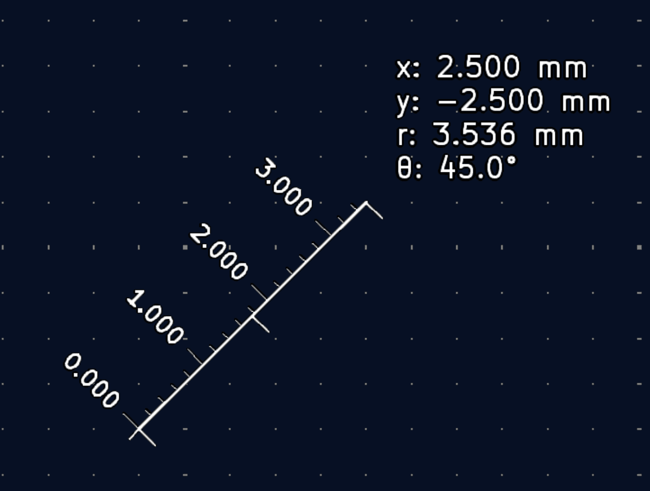
Ask Codex to locate each new test point in the PCB Editor and inspect its surroundings. Use KiCad’s measurement tools where needed, and compare the geometry with the probe or fixture dimensions you supplied.
Source: KiCad Documentation Contributors
Inspect the new test points without editing the board. Report their board side, nearby components, and measured spacing relevant to the supplied probe dimensions. Flag any access question that cannot be resolved from the available views.
A top-down screenshot cannot establish vertical clearance. Use the 3D Viewer to investigate possible obstructions, but verify the component models first. If a tall component lacks a model, an apparently open approach may be misleading.
For an oscilloscope measurement, also inspect where the ground connection would attach. A reachable signal pad alone does not establish a suitable measurement arrangement.

Source: KiCad Documentation Contributors
Cross-probe the intended connection
Use cross-probing to navigate between the schematic test point and its PCB representation. Ask Codex to select the symbol, locate the corresponding footprint, and inspect the pad’s assigned net.
This is particularly useful when references are close together or similar net names appear on different sheets. Have Codex report what the properties and highlighting show, rather than inferring connectivity from screen position.
If the editors display different revisions, stop and reconcile them. Do not use an interface screenshot to overrule conflicting saved-file data without investigating the mismatch.
Make test point labels useful at the bench
A label should help someone identify the measurement point on an assembled board. Codex can inspect whether the reference or approved signal label overlaps another marking, sits across a pad opening, or disappears beneath a component.
If you approve cleanup, restrict the operation to specified silkscreen text. Moving a label should not move its footprint, alter the net, or rename the schematic reference.
Check the result at a meaningful scale. Text that is readable while heavily zoomed in may not be practical on the manufactured board. Use your fabrication provider’s requirements when assessing text size and stroke width.

Source: KiCad Documentation Contributors
Investigate missing libraries instead of hiding warnings
A revision review can also expose an unresolved footprint association or missing 3D model. Codex can navigate the relevant properties and library settings to identify the referenced file, path variable, or model association.
Ask it to propose the smallest correction and explain whether the change affects project-local or global settings. Do not approve a visually similar replacement simply to remove a warning.
End the screen review with observations, measurements, and unresolved questions. That record should distinguish confirmed interface information from assumptions that still require datasheet, mechanical, or hardware verification.

Source: KiCad Documentation Contributors
Turn ERC and DRC Into a Revision Gate
Once the candidate passes visual review, check whether it satisfies the revision’s electrical and layout conditions. Run ERC and DRC against the synchronized, saved files using the same KiCad version and checking settings as the Rev A baseline.
The KiCad CLI can produce machine-readable reports and return a violation-specific exit code:
Replace the example paths with your project files. These commands operate on saved input, not unsaved editor changes. A command that finishes successfully is also different from a report containing no violations. With --exit-code-violations, KiCad returns exit code 5 when the checked violations are present.
Compare findings, not just counts
Ask Codex to classify each finding as new, resolved, or unchanged, using the affected objects and locations where available. An unchanged total can conceal a resolved problem and a newly introduced one.

Source: KiCad Documentation Contributors
Compare Rev A and Rev B reports. Identify new findings associated with the test point additions and any unexpected changes elsewhere. Preserve existing rules and exclusions. Report unresolved issues without modifying the project.
Check zone-fill conditions before interpreting PCB results. KiCad 10 supports --refill-zones, while --schematic-parity enables a schematic-to-PCB consistency check. Apply appropriate options consistently across the comparison, and review exclusions separately.
The revision gate should require correct test point connections, no unapproved design changes, and reviewed findings. Do not let Codex lower clearance limits or suppress violations to make the gate pass.
Passing these checks does not validate probe loading, operating conditions, or real-world circuit behavior. Those remain engineering questions. The gate establishes a documented checking result for this revision, not a guarantee that the board is ready for production.
Make the Release Folder Prove Which Board It Contains
Rev B is not complete when a ZIP file appears. It is complete when you can establish which saved design produced the files, which checks were run, and whether the package includes the approved test point changes.
Freeze the reviewed project state before exporting. Create a dedicated release folder, such as releases/rev-b/, and keep earlier outputs outside it. Do not reuse a directory containing leftover files that could accidentally enter the new archive.
Ask Codex to prepare a release manifest alongside the manufacturing exports:
Manifest entry | What it establishes |
|---|---|
Source revision | Git commit or another recorded project identifier |
Source files | Schematic, PCB, and relevant project settings |
Tool versions | KiCad and connector versions used |
Export settings | Layers, units, origins, and assembly options |
Check reports | ERC/DRC results and unresolved findings |
Output inventory | Filenames and, where useful, file hashes |
A hash helps identify an exact file, but it does not establish that its contents are correct. Likewise, a revision label in a filename is only a claim unless the source record supports it.
Verify the added test points in the outputs
Open the newly exported Gerber and drill files in Gerber Viewer. Codex can use Computer Use to inspect the test point locations across copper, mask, and silkscreen layers. Confirm that the approved pad openings and labels appear in the exported data, not merely in the PCB Editor.
Review BOM and placement handling separately. Bare probe pads are not purchased components; fitted loop-style test points may require assembly entries. Check the chosen footprint attributes and export options against your actual build requirements.
Finally, generate the archive from the reviewed folder and compare its contents with the manifest. Do not assume an existing ZIP reflects newly regenerated files.
Ask Codex to summarize what changed, what was verified, and what remains unresolved. Uploading the package, sharing proprietary design data, or ordering boards should require separate approval after you review that summary.

Source: KiCad Documentation Contributors
Move the Workstation Bottleneck to Vagon
A larger PCB project can turn a quick revision into a workstation problem. Detailed 3D models, analysis tools, multiple schematic sheets, and repeated checking runs all compete for local resources. If your everyday computer is already struggling, adding automation does not remove that bottleneck.
Vagon Cloud Computer provides a remote Windows workstation with selectable CPU, RAM, and GPU configurations. You can access it from your existing device and change performance configurations while retaining the same cloud computer and files.
For this workflow, choose resources around the work you actually perform. CPU performance and memory capacity matter for computational tasks and larger projects. Graphics resources are relevant to interactive visualization, but a powerful GPU should not be treated as an automatic accelerator for ERC or DRC.
The practical benefit is also environmental consistency. Install KiCad, Codex, and the MCP dependencies together, then keep project libraries and release files in that workspace. A connector launched inside the cloud computer can work with files there without relying on paths from your local laptop.
Computer Use needs its own verification. On Windows, it operates in the active desktop session. Run it in the supported desktop environment, approve the necessary app access, and avoid competing mouse or keyboard input. Controlling a local browser showing Vagon is not the same as direct access to KiCad’s windows.
Simple boards may need no additional hardware. When project complexity outgrows your local machine, Vagon gives you a way to scale the workstation without replacing the computer you use every day.
FAQs
Can Codex work with KiCad without an MCP server?
Yes. With appropriate file and shell access, Codex can inspect saved files, write scripts, and invoke KiCad CLI operations. MCP provides a structured tool interface, but it is not required for every task. Computer Use is another separate option for interface-based work.
Does a KiCad MCP connection control the live editor?
Not necessarily. The KiCad Copilot connector used here modifies saved project files. Other connectors may use IPC to communicate with a running editor. Check the specific tool’s backend and synchronization behavior. A connected server does not automatically mean Codex can inspect unsaved changes.
Can Codex modify both schematics and PCB layouts?
A compatible connector can expose operations for both, but support varies by implementation and KiCad version. Treat schematic editing, schematic-to-PCB synchronization, placement, and routing as separate steps. Verify that references and net assignments remain correct after each approved operation rather than assuming a successful response proves consistency.
Does Codex CLI include Computer Use automatically?
No. CLI file and terminal access are not desktop screen control. The Computer Use workflow described here requires a supported desktop environment, the relevant plugin, and permissions. Confirm feature availability in your installation before planning tasks that depend on operating KiCad’s graphical interface.
Can Codex route a board after adding test points?
Some connectors support routing, but a full reroute may be inappropriate for a small revision. Prefer a scoped plan for the approved additions. If the available operation cannot preserve existing copper, stop and choose another method. Review resulting connections and rule-check findings before accepting the candidate.
What if the MCP server changes a file already open in KiCad?
An older editor buffer can overwrite the updated file. Save intentional changes before connector writes, then carefully reload or reopen the affected document afterward. Preserve a recoverable copy first. If both versions contain work you need, reconcile them rather than blindly saving either one.
Can I run this workflow on Vagon?
A compatible Vagon Windows desktop can host KiCad, Codex, and connector dependencies. You still need to configure paths, permissions, and tool access. Verify Computer Use separately in the active desktop session, and test the complete workflow on a project copy before relying on it for production revisions.
Your prototype works, but testing the next batch is harder than it should be. The reset signal is buried beside the microcontroller, the supply rail has no convenient probe point, and the assembly folder contains files from two different revisions. Before ordering Rev B, you need more than a cleaner-looking layout. You need a controlled change and a reliable record of what changed.
Using Codex with KiCad can help connect those tasks. A compatible MCP server gives Codex access to structured project information and supported design operations. Depending on the connector, those operations may modify saved files or communicate with a running editor. Computer Use provides a separate route for navigating KiCad’s interface and inspecting details that need visual context.
Neither connection is a native KiCad feature, and neither guarantees a working circuit. Your connector, KiCad version, desktop environment, and permissions determine what Codex can actually do.
This guide follows an existing microcontroller board from Rev A to Rev B. The goal is to add approved debug access, inspect the result, compare rule-check findings, and prepare a consistent release package without rebuilding unrelated parts of the design.
Source: KiCad Documentation Contributors
Start With a Revision Brief, Not an Open-Ended Design Prompt
For this board, Rev B should improve debug access without redesigning the circuit. Tell Codex which nets need access, why you need it, and which physical constraints must remain unchanged. “Add useful test points” is too broad: Codex would have to guess what you intend to measure and how you will reach it.
Specify the approved nets by their actual project names. Include the probe or fixture requirements where known. A handheld probe, oscilloscope probe, and pogo-pin fixture have different placement needs.
A short revision brief makes the boundary explicit:
Requirement | Acceptance condition |
|---|---|
Debug access | Test points connect only to approved nets |
Mechanical layout | Board outline, mounting holes, and fixed connectors remain unchanged |
Existing circuitry | No unrelated component or net changes |
Identification | Each new test point has an agreed reference and readable label |
Verification | Changes are reviewed against the saved Rev A baseline |
Adding a test point is not electrically neutral in every design. Extra copper, branches, and probe loading can affect sensitive signals. Begin with user-selected low-speed or supply measurement points, and require engineering review before modifying high-speed, RF, or precision analog paths.
Give Codex the brief before enabling writes:
Inspect the project and propose a Rev B plan for the approved debug nets. Do not modify files. Identify what must remain unchanged, suggest test point options, and list the information you need before proceeding.
The first deliverable should be a scoped proposal with unresolved questions, not an edited PCB.
Give Codex Two Different Paths Into KiCad
MCP and Computer Use solve different access problems. The first exposes tools and project data; the second lets Codex inspect and operate the graphical interface. Configure and test them independently so you know which route a task uses.
Connect a file-oriented MCP server
For this walkthrough, KiCad Copilot provides a documented Codex connection. Its requirements include Node.js 20 or newer, KiCad 9 or 10, and Python 3 for component conversion and analysis features.
After reviewing the third-party package, register it with Codex:
The first command configures a local STDIO server launched through npx. It can download and execute the package, so treat it as installing software, not merely adding a bookmark. Record the package version used, and consider a reviewed, pinned version for a repeatable setup.
Codex stores server settings in its MCP configuration. Restart the client after registration, then confirm that the server connects and exposes its tools. A configured entry in codex mcp list is not proof that a project operation succeeds.
Start with an inspection request:
Inspect the project at the supplied absolute path. Report its schematic and PCB files, the discovered KiCad CLI version, and the approved debug nets you can identify. Do not modify, synchronize, or export anything.
Compare the response with your project. If kicad-cli is installed somewhere unusual, the connector supports an explicit KICAD_CLI_PATH setting.
This server edits saved files, not the live editor buffer. Before a write, save intentional KiCad changes. Afterward, reload or reopen the affected document carefully. Do not save an older editor buffer over the updated file. Other connectors may use IPC, but their live-access requirements should not be applied to this setup.
Enable Computer Use separately
In a supported desktop environment, install or enable the Computer Use plugin and review its app access settings. On macOS, grant the required Screen Recording and Accessibility permissions yourself. On Windows, keep KiCad visible in the active desktop session.
Windows Computer Use takes foreground control, so avoid simultaneous mouse or keyboard input during the task. Codex CLI access alone does not provide these desktop capabilities.
For the first screen test, ask Codex to locate the open PCB and report its filename without editing anything. Approve KiCad access when prompted, and stop if it selects the wrong window.
Only proceed when both tests identify the same project. File access and screen access must agree before they can support one revision workflow.
Build a Baseline Codex Can Compare Against
Before adding anything, preserve Rev A as a known starting point. A recoverable project copy or Git commit should include the schematic hierarchy, PCB, project settings, and relevant local libraries. Keep existing manufacturing files separately identified so they cannot be mistaken for the future Rev B outputs.
The baseline needs more than a screenshot. Ask Codex to record the exact project path, KiCad version, sheet structure, and the net connections relevant to your revision. In a hierarchical design, similarly named labels can have different scopes. Confirm the intended connection through the project’s connectivity data rather than matching text alone.
Source: KiCad Documentation Contributors
Capture the objects that matter
For each approved debug net, identify the connected component references and pins, existing access points, and corresponding PCB pads. Also record the fixed objects protected by your revision brief.
A compact baseline might contain:
Baseline item | Purpose |
|---|---|
Approved net and connected pins | Establish the intended electrical connection |
Existing test points or connector access | Avoid unnecessary additions |
Fixed footprint positions and rotations | Detect unintended movement |
Board outline and mounting holes | Preserve mechanical constraints |
ERC and DRC reports | Separate existing findings from new ones |
Existing access is worth checking first. A suitable connector pin or exposed pad may already meet your measurement needs, making another test point unnecessary.
Request a read-only summary:
Build a Rev A baseline for the approved debug nets. List their connected pins, existing access points, and relevant PCB pads. Record protected footprint positions and identify unresolved net-name or hierarchy questions. Do not change the project.
Keep analysis separate from approval
File-based tools such as kicad-happy can support structured review, but their findings still need interpretation. Missing operating conditions, incomplete models, or unsupported cases can limit the analysis. Do not convert a suggested issue directly into an authorized edit.
Run baseline ERC and DRC using the settings you intend to retain for the comparison. Save the reports with the revision record.
Finally, preserve both machine-readable data and a short human-readable summary. A text diff can reveal changed objects, but it does not explain whether a test point is accessible or a new branch is appropriate. Those questions need the design brief and later visual review.
Add Debug Access Without Rebuilding the Board
With the Rev A baseline preserved, turn the approved net list into specific additions. Each test point needs a schematic reference, a verified connection, and a footprint appropriate for the intended probe. Do not let Codex invent library identifiers or choose pad dimensions without considering your measurement setup.
For illustration, suppose the revision brief approves access to RESET_N and +3V3. These are example names, not nets Codex should assume exist in your project. It must resolve the actual connections before proposing changes.
Add the schematic connection first
Ask Codex to find suitable symbols and footprints in the available libraries, then present their identifiers and relevant dimensions. Decide whether you need a bare probe pad, a loop-style component, or a fixture contact. Those choices affect mechanical access and assembly requirements.
Source: KiCad Documentation Contributors
Approve the schematic edit only after reviewing the proposed mapping:
Add the approved test point symbols to the specified sheet and connect each to its confirmed net. Use the agreed references and footprint assignments. Preserve existing components and connections. Stop if the operation requires broader changes, and report the resulting connectivity before updating the PCB.
After the edit, verify that each symbol pin belongs to the intended net. A nearby label or a wire that looks connected is insufficient evidence.
Next, explicitly synchronize the schematic changes with the board. KiCad’s forward annotation transfers design information, but it does not decide where a new footprint should sit or complete its routing. Review synchronization changes for unexpected replacements, removals, or altered net assignments.
Source: KiCad Documentation Contributors
Approve a local placement, not a fresh layout
For each new footprint, specify the intended board side and an acceptable placement region. Consider probe approach, nearby component height, access after assembly, and a suitable ground reference for the measurement.
There is an important connector-specific detail: KiCad Copilot’s documented placement workflow can apply a returned PCB even when producing a preview. A preview filename therefore does not establish that the operation is read-only.
Generate candidates on a disposable project copy unless you have verified the operation’s preservation behavior. If the tool cannot retain existing placement and routing, do not use a full-board layout operation for this small revision. Switch to an explicitly approved KiCad interface operation instead.
Route only the approved additions
Placing a test point does not connect its pad through copper. Identify the remaining connection and approve a local routing plan separately. Do not authorize clearing existing tracks or rerouting every net to solve one new connection.
Finally, compare the updated project with Rev A. Confirm the new references, footprint assignments, pad nets, and routing, while checking that protected objects remain unchanged. Preserve this candidate revision for the screen-based review before preparing any manufacturing files.
Use the Screen to Check What the Data Cannot Show
The revised project may contain the correct nets and footprints while still being awkward to test. A probe pad can sit beneath an overhanging component, its label can be unreadable, or the 3D model needed to assess access can be missing.
Computer Use gives Codex a way to investigate those questions inside KiCad. These are practical inspection workflows to try, not guarantees of correct visual judgment. Start with read-only tasks and authorize any interface-based edits separately.
Check whether the probe can reach the pad
Ask Codex to locate each new test point in the PCB Editor and inspect its surroundings. Use KiCad’s measurement tools where needed, and compare the geometry with the probe or fixture dimensions you supplied.
Source: KiCad Documentation Contributors
Inspect the new test points without editing the board. Report their board side, nearby components, and measured spacing relevant to the supplied probe dimensions. Flag any access question that cannot be resolved from the available views.
A top-down screenshot cannot establish vertical clearance. Use the 3D Viewer to investigate possible obstructions, but verify the component models first. If a tall component lacks a model, an apparently open approach may be misleading.
For an oscilloscope measurement, also inspect where the ground connection would attach. A reachable signal pad alone does not establish a suitable measurement arrangement.
Source: KiCad Documentation Contributors
Cross-probe the intended connection
Use cross-probing to navigate between the schematic test point and its PCB representation. Ask Codex to select the symbol, locate the corresponding footprint, and inspect the pad’s assigned net.
This is particularly useful when references are close together or similar net names appear on different sheets. Have Codex report what the properties and highlighting show, rather than inferring connectivity from screen position.
If the editors display different revisions, stop and reconcile them. Do not use an interface screenshot to overrule conflicting saved-file data without investigating the mismatch.
Make test point labels useful at the bench
A label should help someone identify the measurement point on an assembled board. Codex can inspect whether the reference or approved signal label overlaps another marking, sits across a pad opening, or disappears beneath a component.
If you approve cleanup, restrict the operation to specified silkscreen text. Moving a label should not move its footprint, alter the net, or rename the schematic reference.
Check the result at a meaningful scale. Text that is readable while heavily zoomed in may not be practical on the manufactured board. Use your fabrication provider’s requirements when assessing text size and stroke width.
Source: KiCad Documentation Contributors
Investigate missing libraries instead of hiding warnings
A revision review can also expose an unresolved footprint association or missing 3D model. Codex can navigate the relevant properties and library settings to identify the referenced file, path variable, or model association.
Ask it to propose the smallest correction and explain whether the change affects project-local or global settings. Do not approve a visually similar replacement simply to remove a warning.
End the screen review with observations, measurements, and unresolved questions. That record should distinguish confirmed interface information from assumptions that still require datasheet, mechanical, or hardware verification.
Source: KiCad Documentation Contributors
Turn ERC and DRC Into a Revision Gate
Once the candidate passes visual review, check whether it satisfies the revision’s electrical and layout conditions. Run ERC and DRC against the synchronized, saved files using the same KiCad version and checking settings as the Rev A baseline.
The KiCad CLI can produce machine-readable reports and return a violation-specific exit code:
Replace the example paths with your project files. These commands operate on saved input, not unsaved editor changes. A command that finishes successfully is also different from a report containing no violations. With --exit-code-violations, KiCad returns exit code 5 when the checked violations are present.
Compare findings, not just counts
Ask Codex to classify each finding as new, resolved, or unchanged, using the affected objects and locations where available. An unchanged total can conceal a resolved problem and a newly introduced one.
Source: KiCad Documentation Contributors
Compare Rev A and Rev B reports. Identify new findings associated with the test point additions and any unexpected changes elsewhere. Preserve existing rules and exclusions. Report unresolved issues without modifying the project.
Check zone-fill conditions before interpreting PCB results. KiCad 10 supports --refill-zones, while --schematic-parity enables a schematic-to-PCB consistency check. Apply appropriate options consistently across the comparison, and review exclusions separately.
The revision gate should require correct test point connections, no unapproved design changes, and reviewed findings. Do not let Codex lower clearance limits or suppress violations to make the gate pass.
Passing these checks does not validate probe loading, operating conditions, or real-world circuit behavior. Those remain engineering questions. The gate establishes a documented checking result for this revision, not a guarantee that the board is ready for production.
Make the Release Folder Prove Which Board It Contains
Rev B is not complete when a ZIP file appears. It is complete when you can establish which saved design produced the files, which checks were run, and whether the package includes the approved test point changes.
Freeze the reviewed project state before exporting. Create a dedicated release folder, such as releases/rev-b/, and keep earlier outputs outside it. Do not reuse a directory containing leftover files that could accidentally enter the new archive.
Ask Codex to prepare a release manifest alongside the manufacturing exports:
Manifest entry | What it establishes |
|---|---|
Source revision | Git commit or another recorded project identifier |
Source files | Schematic, PCB, and relevant project settings |
Tool versions | KiCad and connector versions used |
Export settings | Layers, units, origins, and assembly options |
Check reports | ERC/DRC results and unresolved findings |
Output inventory | Filenames and, where useful, file hashes |
A hash helps identify an exact file, but it does not establish that its contents are correct. Likewise, a revision label in a filename is only a claim unless the source record supports it.
Verify the added test points in the outputs
Open the newly exported Gerber and drill files in Gerber Viewer. Codex can use Computer Use to inspect the test point locations across copper, mask, and silkscreen layers. Confirm that the approved pad openings and labels appear in the exported data, not merely in the PCB Editor.
Review BOM and placement handling separately. Bare probe pads are not purchased components; fitted loop-style test points may require assembly entries. Check the chosen footprint attributes and export options against your actual build requirements.
Finally, generate the archive from the reviewed folder and compare its contents with the manifest. Do not assume an existing ZIP reflects newly regenerated files.
Ask Codex to summarize what changed, what was verified, and what remains unresolved. Uploading the package, sharing proprietary design data, or ordering boards should require separate approval after you review that summary.
Source: KiCad Documentation Contributors
Move the Workstation Bottleneck to Vagon
A larger PCB project can turn a quick revision into a workstation problem. Detailed 3D models, analysis tools, multiple schematic sheets, and repeated checking runs all compete for local resources. If your everyday computer is already struggling, adding automation does not remove that bottleneck.
Vagon Cloud Computer provides a remote Windows workstation with selectable CPU, RAM, and GPU configurations. You can access it from your existing device and change performance configurations while retaining the same cloud computer and files.
For this workflow, choose resources around the work you actually perform. CPU performance and memory capacity matter for computational tasks and larger projects. Graphics resources are relevant to interactive visualization, but a powerful GPU should not be treated as an automatic accelerator for ERC or DRC.
The practical benefit is also environmental consistency. Install KiCad, Codex, and the MCP dependencies together, then keep project libraries and release files in that workspace. A connector launched inside the cloud computer can work with files there without relying on paths from your local laptop.
Computer Use needs its own verification. On Windows, it operates in the active desktop session. Run it in the supported desktop environment, approve the necessary app access, and avoid competing mouse or keyboard input. Controlling a local browser showing Vagon is not the same as direct access to KiCad’s windows.
Simple boards may need no additional hardware. When project complexity outgrows your local machine, Vagon gives you a way to scale the workstation without replacing the computer you use every day.
FAQs
Can Codex work with KiCad without an MCP server?
Yes. With appropriate file and shell access, Codex can inspect saved files, write scripts, and invoke KiCad CLI operations. MCP provides a structured tool interface, but it is not required for every task. Computer Use is another separate option for interface-based work.
Does a KiCad MCP connection control the live editor?
Not necessarily. The KiCad Copilot connector used here modifies saved project files. Other connectors may use IPC to communicate with a running editor. Check the specific tool’s backend and synchronization behavior. A connected server does not automatically mean Codex can inspect unsaved changes.
Can Codex modify both schematics and PCB layouts?
A compatible connector can expose operations for both, but support varies by implementation and KiCad version. Treat schematic editing, schematic-to-PCB synchronization, placement, and routing as separate steps. Verify that references and net assignments remain correct after each approved operation rather than assuming a successful response proves consistency.
Does Codex CLI include Computer Use automatically?
No. CLI file and terminal access are not desktop screen control. The Computer Use workflow described here requires a supported desktop environment, the relevant plugin, and permissions. Confirm feature availability in your installation before planning tasks that depend on operating KiCad’s graphical interface.
Can Codex route a board after adding test points?
Some connectors support routing, but a full reroute may be inappropriate for a small revision. Prefer a scoped plan for the approved additions. If the available operation cannot preserve existing copper, stop and choose another method. Review resulting connections and rule-check findings before accepting the candidate.
What if the MCP server changes a file already open in KiCad?
An older editor buffer can overwrite the updated file. Save intentional changes before connector writes, then carefully reload or reopen the affected document afterward. Preserve a recoverable copy first. If both versions contain work you need, reconcile them rather than blindly saving either one.
Can I run this workflow on Vagon?
A compatible Vagon Windows desktop can host KiCad, Codex, and connector dependencies. You still need to configure paths, permissions, and tool access. Verify Computer Use separately in the active desktop session, and test the complete workflow on a project copy before relying on it for production revisions.
Get Beyond Your Computer Performance
Run applications on your cloud computer with the latest generation hardware. No more crashes or lags.

Trial includes 1 hour usage + 7 days of storage.
Summarize with AI

Ready to focus on your creativity?
Vagon gives you the ability to create & render projects, collaborate, and stream applications with the power of the best hardware.

Vagon Blog
Run heavy applications on any device with
your personal computer on the cloud.
San Francisco, California
Solutions
Vagon Teams
Vagon Streams
Use Cases
Resources
Vagon Blog
How to Use ComfyUI With Claude: MCP & Computer Use Guide
How to Use Rhino With Codex: MCP & Computer Use Guide
How to Use KiCad With Codex: MCP & Computer Use Guide
How to Use KiCad With Claude: MCP & Computer Use Guide Meta
How to Use FreeCAD With Codex: MCP & Computer Use
How to Use FreeCAD With Claude: MCP & Computer Use
How to Use 3ds Max With Codex: MCP & Computer Use
How to Use Houdini With Claude: MCP & Computer Use
How to Use Cinema 4D With Claude: MCP & Computer Use
Vagon Blog
Run heavy applications on any device with
your personal computer on the cloud.
San Francisco, California
Solutions
Vagon Teams
Vagon Streams
Use Cases
Resources
Vagon Blog
How to Use ComfyUI With Claude: MCP & Computer Use Guide
How to Use Rhino With Codex: MCP & Computer Use Guide
How to Use KiCad With Codex: MCP & Computer Use Guide
How to Use KiCad With Claude: MCP & Computer Use Guide Meta
How to Use FreeCAD With Codex: MCP & Computer Use
How to Use FreeCAD With Claude: MCP & Computer Use
How to Use 3ds Max With Codex: MCP & Computer Use
How to Use Houdini With Claude: MCP & Computer Use
How to Use Cinema 4D With Claude: MCP & Computer Use
Vagon Blog
Run heavy applications on any device with
your personal computer on the cloud.
San Francisco, California
Solutions
Vagon Teams
Vagon Streams
Use Cases
Resources
Vagon Blog