Instant Connection for Pixel Streaming
— New Feature Automated Setup

How to Use FreeCAD With Claude: MCP & Computer Use
Architecture
-
How to Use FreeCAD With Claude: MCP & Computer Use
Architecture
How to Use FreeCAD With Claude: MCP & Computer Use
Architecture
-
Table of Contents
A mounting bracket looks correct in FreeCAD until you change the distance between its holes. The sketch shifts, a pocket fails, or a fillet no longer references the intended edge. The original shape was convincing, but the model did not preserve the relationships that made it useful.
That is the difference between asking Claude to generate geometry and using it to help build an editable design. A practical FreeCAD workflow needs explicit dimensions, meaningful constraints, and checks after each important change.
Through a compatible MCP connector, Claude can inspect open documents, edit object properties, and execute Python inside FreeCAD. This requires a third-party addon and a configured local connection; it is not a native Claude feature built into FreeCAD.
Computer Use provides a separate way to navigate the interface and review visible results, such as Sketcher messages or drawing layouts. Its availability depends on your Claude setup and supported platform.
This guide follows a bracket from its design brief through controlled parameter changes and export checks. The goal is not simply to produce a solid, but to retain a model you can understand, revise, and verify.

Source: FreeCAD
What Claude Needs to Understand Before It Touches Your Model
FreeCAD models contain more than the geometry visible in the viewport. A document can include Bodies, sketches, construction geometry, and features that depend on earlier operations. Claude needs that structure to make a targeted edit rather than recreate the part.
For the bracket example, “increase the thickness” is incomplete. Does thickness come from a Pad length, a spreadsheet value, or an expression? Changing the final shape directly may bypass the parameter you intended to control.
The access method determines what Claude can establish:
Access method | What it enables |
|---|---|
Code generation | Produces a script for you to review and run. |
MCP | Queries and performs supported operations inside FreeCAD. |
Computer Use | Inspects and operates the approved application’s interface. |
Even with live access, object identification matters. FreeCAD distinguishes an object’s internal Name from its displayed Label. Labels can be edited and may not uniquely identify an object. Ask Claude to confirm the document, internal object name, and relevant properties before making changes.
It should also distinguish an editable feature sequence from a finished shape. Python can create a solid without creating the Sketch, Pad, and Pocket history you expect. If future changes matter, specify the required model structure.
A useful starting brief is:
Inspect the active document without changing it. Identify the bracket’s Body, sketches, controlling dimensions, and downstream features. Report dimensions with units and distinguish editable parameters from calculated values.
Finally, describe design intent: which holes must remain concentric, what must stay symmetrical, and which dimensions may change independently. Neither MCP access nor screen control can infer those requirements reliably from appearance alone.
Set Up the FreeCAD Bridge and Verify the Connection
For this walkthrough, we will use the community-maintained FreeCAD MCP connector. Its architecture has two parts: an addon running inside FreeCAD and an MCP server launched by Claude. Both must be working before Claude can inspect your document.
Follow this connector’s installation instructions throughout. Other projects with similar names use different workbenches, transports, and configuration options.
Start the Addon Inside FreeCAD
Install FreeCAD and the uv tooling required by the connector. Clone the repository, then copy its addon/FreeCADMCP directory into the appropriate FreeCAD addon directory for your operating system.
The project’s installation guide provides platform-specific paths and setup instructions. Avoid copying files into an assumed location, especially if you have multiple FreeCAD installations.
Restart FreeCAD, select the MCP Addon workbench, and click Start RPC Server in the FreeCAD MCP toolbar. Keep FreeCAD open while using the connection.
Begin with a disposable document. Review the addon before installing it, since its Python execution capabilities operate with FreeCAD’s privileges and can affect more than the visible model.

Source: neka-nat/freecad-mcp
Connect the Local MCP Server to Claude
The repository documents this entry for claude_desktop_config.json:
{
  "mcpServers": {
    "freecad": {
      "command": "uvx",
      "args": ["freecad-mcp"]
{
  "mcpServers": {
    "freecad": {
      "command": "uvx",
      "args": ["freecad-mcp"]
Merge the entry into your existing configuration rather than replacing unrelated servers. Restart Claude Desktop after saving it. If the server fails to launch, verify that Claude can locate uvx and review the connection logs.
This is a local application connection, not a cloud service added through a public URL. Claude’s desktop and web connectors have different availability rules. Use a desktop session that exposes the configured local tools.
Computer Use requires separate enablement and application permissions. Registering this server does not grant Claude mouse or keyboard access.
Run a Read-Only Connection Test
With your test document open, ask:
Use the FreeCAD MCP tools to list open documents. Identify the document containing my bracket and report its objects, internal names, labels, and types. Do not create, edit, delete, recompute, or save anything.
The connector documents list_documents, get_objects, and get_object for these queries. Compare Claude’s response with FreeCAD’s model tree before authorizing changes.
If the document is missing or the connection fails, resolve that first. A configured server does not prove that the FreeCAD addon is responding. Once the report matches your test document, you have a verified starting point for modeling.
Build a Bracket That Can Survive a Dimension Change
Start with a simple mounting plate before adding bends or other features. It gives you a manageable test of whether Claude can preserve design relationships rather than merely produce the requested silhouette.
For this example, use a rectangular plate with two mounting holes. Treat the dimensions as demonstration values, not manufacturing recommendations.
Turn the Brief Into Named Parameters
Define the inputs and their relationships before modeling:
Parameter | Example value | Design intent |
|---|---|---|
Width | 60 mm | Plate centered on the sketch origin |
Height | 30 mm | Symmetrical about the horizontal axis |
Thickness | 4 mm | Controlled by the extrusion length |
Hole diameter | 5 mm | Equal diameter for both holes |
Hole spacing | 40 mm | Hole centers positioned symmetrically |
Specify that hole spacing means center-to-center distance. Otherwise, Claude could interpret it as the gap between hole edges.
Ask Claude to identify any missing requirements before proceeding. Edge clearance, fit, loading, and material are separate design decisions; the assistant should not silently choose them.

Source: FreeCAD News
Preserve an Editable Feature Sequence
Request a PartDesign Body containing a constrained plate sketch, a Pad for thickness, and a hole sketch followed by a Pocket. The precise structure can vary, but the controlling dimensions should remain accessible.
A useful prompt is:
Create a new document for this demonstration plate using the listed dimensions. Build an editable PartDesign feature sequence, not only a final solid. Keep the plate centered, make the holes equal in diameter, and position their centers symmetrically. Report the controlling objects and constraints. Do not modify another document or export files.
Have Claude explain how the hole sketch is supported. Attaching to a generated face and using a principal plane or datum-based reference create different dependencies. Choose the approach deliberately rather than accepting whichever face happens to be selected.
Creating a solid through Python does not prove that this feature structure exists. Inspect the model tree and controlling properties after creation.
Test the Intended Change
Before adding fillets, change the hole spacing from 40 mm to 44 mm. Recompute the document, then ask Claude to verify that both holes moved symmetrically while their diameter, plate dimensions, and thickness remained unchanged.
Check the result numerically and visually. There should still be one intended solid, with two through-holes and no failed downstream features.
If the test fails, repair the controlling sketch or dependency rather than patching the final shape. Save the verified .FCStd model as a checkpoint before introducing additional complexity.
Diagnose Sketch Problems Without Deleting Design Intent
A sketch error is not a request to remove constraints until the warning disappears. Constraints encode relationships, and deleting the wrong one can produce a model that recomputes but no longer follows the brief.
Suppose the bracket’s holes must remain equal in diameter and symmetrical about the origin. Claude adds a diameter constraint to each circle, then adds an equality constraint. Depending on the existing constraints, that extra relationship may be redundant. The right repair depends on which dimensions should control the design.

Source: FreeCAD
Separate Missing Constraints From Conflicting Ones
An under-constrained sketch retains movement or dimensional freedom. That may be intentional during construction, but it needs review before the sketch becomes a stable input to downstream features.
Redundant constraints express relationships already enforced elsewhere. Conflicting constraints impose incompatible requirements. These situations need different responses; “fully constrain the sketch” is not a diagnosis.
Ask Claude to inspect before editing:
Review the hole sketch without changing it. Report the solver status, remaining degrees of freedom, and any identified redundant or conflicting constraints. Explain which constraints control diameter, spacing, and symmetry. Propose a minimal repair that preserves those relationships, then wait for approval.
Where the MCP tools do not expose the required details directly, Claude may need a reviewed Python query or a visual inspection of the Sketcher task panel. It should identify unavailable information rather than infer solver status from the sketch’s appearance.
Keep Controlling Dimensions Distinct From Measurements
A driving dimensional constraint sets a value. A reference dimension reports a measurement without controlling the geometry. Converting one into the other can change how the sketch responds to future edits.
For our equal-sized holes, one diameter constraint plus an equality relationship may express the intent more clearly than independently controlling both diameters. However, Claude should inspect the existing setup before making that substitution.
After approving a repair, change the relevant parameter again and recompute. Verify that the expected movement occurs and that unrelated geometry stays fixed. Computer Use can help confirm the visible solver messages and constraint annotations.
A fully constrained sketch is useful evidence of stability, not proof of correctness. It can still contain the wrong dimensions or relationships. Finish by comparing the sketch against the design brief, not merely checking that the solver warning is gone.
Where Computer Use Adds Value in FreeCAD
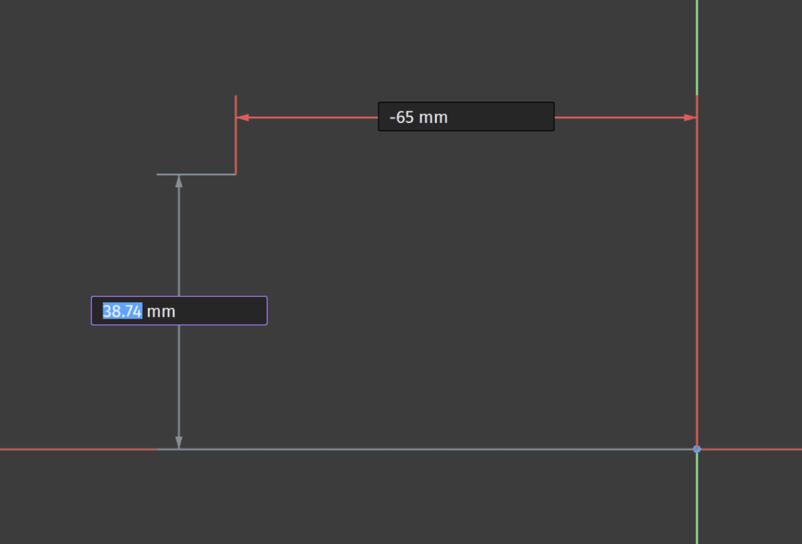
Structured access is usually the better route for reading dimensions and changing known properties. Computer Use becomes useful when the task depends on what FreeCAD displays: a selected face, a solver message, or a drawing page whose annotations overlap.
Enable Computer Use separately in your supported Claude Desktop setup, then approve access to FreeCAD. Availability depends on your plan and platform. Keep the application and required files accessible, and start with a narrow inspection task rather than unrestricted modeling.
Source: FreeCAD News
Match a Model to a Dimensioned Drawing
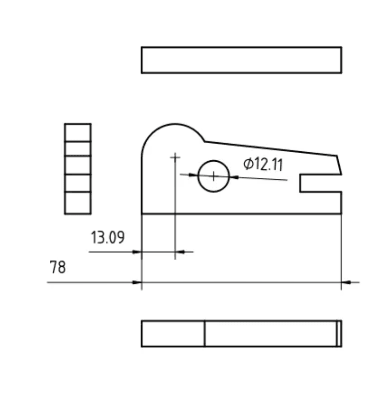
Give Claude a legible drawing and ask it to extract the explicit dimensions into a checklist before modifying the model. It should distinguish stated measurements from assumptions, especially where a view omits depth, tolerances, or hole details.
A suitable request is:
Compare this drawing with the open bracket model. List explicit dimensions and identify missing or ambiguous requirements. Use model properties for numerical checks and the interface for visual comparison. Do not estimate dimensions from screenshot pixels or change the model yet.
The connector includes a 2D-drawing modeling demo, but that does not establish reliable interpretation of every technical drawing. Treat unclear symbols or incomplete views as questions for the user.
Confirm the Selected Face or Sketch Support
A face can look correct while belonging to a different feature than expected. Before attaching a sketch or applying a fillet, ask Claude to inspect both the visible selection and the underlying object reference.
Computer Use can help navigate the model tree, highlight the target, and inspect the property panel. MCP or Python queries can then establish the support relationship more precisely.
After a parameter change, check the reference again. Do not assume an earlier face selection still represents the intended surface.
Review a TechDraw Page Before Delivery
A drawing can contain correct geometry while remaining difficult to read. Claude can inspect a TechDraw page for clipped views, overlapping dimensions, unreadable text, or an unsuitable page scale.
Scope the review explicitly:
Inspect the drawing page without editing it. Identify annotations that overlap, views outside the page boundary, and dimensions that are difficult to read. Report proposed adjustments separately from missing engineering information.
These are proposed Computer Use workflows, not claims of a tested end-to-end drawing assistant. Visual review also cannot certify drawing completeness or manufacturing suitability.
Finally, remember that the MCP connector’s viewport screenshot tool is not equivalent to interface control. Returning an image lets Claude inspect appearance; navigating panels and changing controls requires a separate authorized interaction capability.
Source: FreeCAD
Change Parameters, Then Check the Dependency Chain
Once the bracket passes its first edit test, you can use Claude to prepare a small family of variants. The objective is to change known inputs while preserving the relationships established in the original model.
Begin by asking Claude where each dimension is controlled. An existing document may use sketch constraints, feature properties, spreadsheet cells, or expressions. Adding another control system without inspecting those relationships can create competing sources of truth.

Source: FreeCAD Documentation
Keep One Source of Truth for Each Dimension
Named constraints or spreadsheet aliases can make parameters easier to identify. Expressions can connect those values to downstream properties, reducing repeated manual entry. However, an expression-driven property should usually be changed through its controlling input rather than by replacing the expression.

Source: FreeCAD Documentation
For the bracket, define a bounded variation matrix:
Variant | Width | Thickness | Hole spacing |
|---|---|---|---|
Baseline | 60 mm | 4 mm | 40 mm |
Wider mount | 70 mm | 4 mm | 50 mm |
Thicker plate | 60 mm | 6 mm | 40 mm |
Keep hole diameter and symmetry unchanged. Save each approved variant separately if you need independently recoverable deliverables.
A useful request is:
Identify the existing inputs controlling width, thickness, and hole spacing. Prepare these variants one at a time. After each change, recompute and report feature errors, final dimensions, solid count, and whether the holes remain symmetrical. Preserve expressions and stop if a dependency fails.
Inspect Downstream Features After Every Change
A successful parameter update does not establish that every dependent feature rebuilt correctly. Check the Body’s final feature, sketch support references, and any fillets or other features added later.
FreeCAD’s topological naming improvements reduce problems associated with changing geometry, but they do not remove the need for verification. A valid reference can still point to geometry that no longer matches your design intent.
Compare each result numerically and visually. Confirm the expected dimensions and number of solids, then inspect hole positions and edge treatment. If one variant fails, retain the last verified version and investigate the earliest failing feature. Do not continue generating exports from a partially recomputed document.
Validate the Model Before Exporting STEP or STL
Before exporting, separate three questions: did the script finish, is the geometry valid, and does the part meet the brief? These are different tests. The connector’s execution documentation explicitly warns that script success does not certify geometry validity.
Ask Claude to inspect the final feature after recompute. Check for reported errors, an empty shape, unexpected solid counts, and dimensions outside the approved values. Use FreeCAD’s geometry checks where appropriate, but do not treat a clean result as proof of strength, fit, or manufacturability.
Choose the File for Its Intended Purpose
Keep the .FCStd document as the editable source. STEP is suitable for exchanging CAD geometry, but an exported STEP file should not be assumed to retain FreeCAD’s Sketch, Pad, and Pocket history. STL represents a triangulated surface for workflows such as slicing, rather than an editable parametric model.

Source: XSim
For either export, identify the intended final object explicitly. Selecting intermediate features or multiple overlapping objects can produce the wrong deliverable.
A bounded request is:
Validate the final bracket against the approved dimensions. Report geometry errors and solid count. Propose STEP and STL exports from the final object only, with separate filenames. Wait for approval before writing or overwriting files.
Reopen the Export and Compare It
After approval, reopen each exported file in a separate document. Compare overall dimensions, orientation, and object or solid structure where the format supports it. For STL, check the receiving application’s unit interpretation and review tessellation settings: a coarse mesh can visibly approximate curved holes.
Inspect the exported result, not just the original viewport. Verify that the intended holes and features remain present.
These checks support a reliable handoff, not engineering certification. Material selection, tolerances, loading, and physical fit still require appropriate human review before manufacturing.

Source: XSim
Recover From Errors Without Making the Model Worse
When an operation fails, first establish what changed. A Python exception may occur after objects were created or properties updated. Repeating the same request immediately can add duplicate features or compound a partially completed edit.
Save versioned .FCStd checkpoints before substantial changes. Document transactions can help group edits, but they are not a universal rollback for exported files, external scripts, or every addon operation.
Timeouts need particular care. The connector’s execution documentation explains that an operation already running on the GUI thread can continue after a timeout response. Ask Claude to check RPC or job status before retrying.
Choose the execution route deliberately:
GUI execution: For ordinary document and interface operations.
Background execution: For independent computations, with document access handed back to the GUI thread.
Headless execution: For suitable work in a separate FreeCAD process, followed by explicit file and document synchronization.
A separate process can isolate some failures, but it does not validate the resulting model.
Finally, treat Python execution as application-level access, not a restricted modeling sandbox. Review third-party addons, limit the files placed in scope, and require approval before deletion, overwriting, or running unfamiliar code. If recovery is uncertain, restore the last verified checkpoint.
Give Larger FreeCAD Projects More Room With Vagon
Claude can help organize a modeling workflow, but complex geometry still takes computing resources. Large STEP imports, detailed assemblies, and demanding Boolean operations can leave a modest laptop waiting while FreeCAD processes the next change.
Vagon Cloud Computer gives you a configurable Windows workspace accessible from your existing device. Instead of replacing your laptop to accommodate a heavier project, you can choose a cloud performance configuration and adjust it as your requirements grow.
For this workflow, a practical starting point is to run FreeCAD, Claude Desktop, and the local MCP components in the same cloud Windows environment. This keeps the addon and server close to the application they control. Bring your project files and required workbenches, then verify the connection with a disposable document before opening production work.
Choose performance around the operation, not simply the largest GPU. CPU performance and available RAM matter for many geometry and document tasks. A GPU can support viewport work, but it should not be presented as a universal accelerator for recompute, CAD kernels, or every solver.
Use a representative import, parameter change, and export to evaluate the configuration. Keep project assets in persistent storage and save verified checkpoints.
If you plan to add Computer Use, test application access and session behavior separately. This is a proposed deployment approach, not a preconfigured or certified Claude-FreeCAD integration.
FAQs
Can Claude create editable FreeCAD models?
Yes, through a compatible connector and appropriate Python operations. Specify that you need sketches, constraints, and an editable feature sequence. Creating a final solid alone does not guarantee a parametrically editable model.
Is the FreeCAD MCP connector an official integration?
The connector used in this guide is community-maintained. It is not a native integration supplied by FreeCAD or Anthropic. Review its requirements, permissions, and documentation before installing it.
Do I need Computer Use if I already have MCP?
Not necessarily. MCP can handle supported document queries and modeling operations. Computer Use adds interface navigation and visual checks when structured tools do not cover the task. A viewport screenshot tool does not automatically provide interface control.
Can Claude work from a 2D technical drawing?
The connector includes a drawing-based modeling demo. For your own drawings, provide legible dimensions and clarify missing views, units, and tolerances. Claude should ask about ambiguous requirements rather than estimate precise dimensions from pixels.
Can Claude fix Sketcher constraint errors?
It can help inspect solver information and propose repairs. Require it to explain which relationships a change preserves. Removing a warning is not enough if the sketch loses symmetry, dimensional control, or another intended relationship.
Does a successful recompute prove the part is correct?
No. Check geometry, dimensions, dependencies, and design requirements separately. A model can recompute successfully while containing the wrong hole spacing or an unsuitable feature.
Can Claude run FEM analysis in FreeCAD?
The example connector exposes a CalculiX analysis tool. Meaningful results still depend on appropriate materials, loads, constraints, mesh quality, and engineering review.
Can this workflow run on Windows, macOS, or Linux?
FreeCAD is cross-platform, but connector requirements and Claude access differ. Verify each component separately. Claude Desktop Computer Use support should not be inferred from FreeCAD’s operating-system support.
A mounting bracket looks correct in FreeCAD until you change the distance between its holes. The sketch shifts, a pocket fails, or a fillet no longer references the intended edge. The original shape was convincing, but the model did not preserve the relationships that made it useful.
That is the difference between asking Claude to generate geometry and using it to help build an editable design. A practical FreeCAD workflow needs explicit dimensions, meaningful constraints, and checks after each important change.
Through a compatible MCP connector, Claude can inspect open documents, edit object properties, and execute Python inside FreeCAD. This requires a third-party addon and a configured local connection; it is not a native Claude feature built into FreeCAD.
Computer Use provides a separate way to navigate the interface and review visible results, such as Sketcher messages or drawing layouts. Its availability depends on your Claude setup and supported platform.
This guide follows a bracket from its design brief through controlled parameter changes and export checks. The goal is not simply to produce a solid, but to retain a model you can understand, revise, and verify.
Source: FreeCAD
What Claude Needs to Understand Before It Touches Your Model
FreeCAD models contain more than the geometry visible in the viewport. A document can include Bodies, sketches, construction geometry, and features that depend on earlier operations. Claude needs that structure to make a targeted edit rather than recreate the part.
For the bracket example, “increase the thickness” is incomplete. Does thickness come from a Pad length, a spreadsheet value, or an expression? Changing the final shape directly may bypass the parameter you intended to control.
The access method determines what Claude can establish:
Access method | What it enables |
|---|---|
Code generation | Produces a script for you to review and run. |
MCP | Queries and performs supported operations inside FreeCAD. |
Computer Use | Inspects and operates the approved application’s interface. |
Even with live access, object identification matters. FreeCAD distinguishes an object’s internal Name from its displayed Label. Labels can be edited and may not uniquely identify an object. Ask Claude to confirm the document, internal object name, and relevant properties before making changes.
It should also distinguish an editable feature sequence from a finished shape. Python can create a solid without creating the Sketch, Pad, and Pocket history you expect. If future changes matter, specify the required model structure.
A useful starting brief is:
Inspect the active document without changing it. Identify the bracket’s Body, sketches, controlling dimensions, and downstream features. Report dimensions with units and distinguish editable parameters from calculated values.
Finally, describe design intent: which holes must remain concentric, what must stay symmetrical, and which dimensions may change independently. Neither MCP access nor screen control can infer those requirements reliably from appearance alone.
Set Up the FreeCAD Bridge and Verify the Connection
For this walkthrough, we will use the community-maintained FreeCAD MCP connector. Its architecture has two parts: an addon running inside FreeCAD and an MCP server launched by Claude. Both must be working before Claude can inspect your document.
Follow this connector’s installation instructions throughout. Other projects with similar names use different workbenches, transports, and configuration options.
Start the Addon Inside FreeCAD
Install FreeCAD and the uv tooling required by the connector. Clone the repository, then copy its addon/FreeCADMCP directory into the appropriate FreeCAD addon directory for your operating system.
The project’s installation guide provides platform-specific paths and setup instructions. Avoid copying files into an assumed location, especially if you have multiple FreeCAD installations.
Restart FreeCAD, select the MCP Addon workbench, and click Start RPC Server in the FreeCAD MCP toolbar. Keep FreeCAD open while using the connection.
Begin with a disposable document. Review the addon before installing it, since its Python execution capabilities operate with FreeCAD’s privileges and can affect more than the visible model.
Source: neka-nat/freecad-mcp
Connect the Local MCP Server to Claude
The repository documents this entry for claude_desktop_config.json:
{
  "mcpServers": {
    "freecad": {
      "command": "uvx",
      "args": ["freecad-mcp"]
Merge the entry into your existing configuration rather than replacing unrelated servers. Restart Claude Desktop after saving it. If the server fails to launch, verify that Claude can locate uvx and review the connection logs.
This is a local application connection, not a cloud service added through a public URL. Claude’s desktop and web connectors have different availability rules. Use a desktop session that exposes the configured local tools.
Computer Use requires separate enablement and application permissions. Registering this server does not grant Claude mouse or keyboard access.
Run a Read-Only Connection Test
With your test document open, ask:
Use the FreeCAD MCP tools to list open documents. Identify the document containing my bracket and report its objects, internal names, labels, and types. Do not create, edit, delete, recompute, or save anything.
The connector documents list_documents, get_objects, and get_object for these queries. Compare Claude’s response with FreeCAD’s model tree before authorizing changes.
If the document is missing or the connection fails, resolve that first. A configured server does not prove that the FreeCAD addon is responding. Once the report matches your test document, you have a verified starting point for modeling.
Build a Bracket That Can Survive a Dimension Change
Start with a simple mounting plate before adding bends or other features. It gives you a manageable test of whether Claude can preserve design relationships rather than merely produce the requested silhouette.
For this example, use a rectangular plate with two mounting holes. Treat the dimensions as demonstration values, not manufacturing recommendations.
Turn the Brief Into Named Parameters
Define the inputs and their relationships before modeling:
Parameter | Example value | Design intent |
|---|---|---|
Width | 60 mm | Plate centered on the sketch origin |
Height | 30 mm | Symmetrical about the horizontal axis |
Thickness | 4 mm | Controlled by the extrusion length |
Hole diameter | 5 mm | Equal diameter for both holes |
Hole spacing | 40 mm | Hole centers positioned symmetrically |
Specify that hole spacing means center-to-center distance. Otherwise, Claude could interpret it as the gap between hole edges.
Ask Claude to identify any missing requirements before proceeding. Edge clearance, fit, loading, and material are separate design decisions; the assistant should not silently choose them.
Source: FreeCAD News
Preserve an Editable Feature Sequence
Request a PartDesign Body containing a constrained plate sketch, a Pad for thickness, and a hole sketch followed by a Pocket. The precise structure can vary, but the controlling dimensions should remain accessible.
A useful prompt is:
Create a new document for this demonstration plate using the listed dimensions. Build an editable PartDesign feature sequence, not only a final solid. Keep the plate centered, make the holes equal in diameter, and position their centers symmetrically. Report the controlling objects and constraints. Do not modify another document or export files.
Have Claude explain how the hole sketch is supported. Attaching to a generated face and using a principal plane or datum-based reference create different dependencies. Choose the approach deliberately rather than accepting whichever face happens to be selected.
Creating a solid through Python does not prove that this feature structure exists. Inspect the model tree and controlling properties after creation.
Test the Intended Change
Before adding fillets, change the hole spacing from 40 mm to 44 mm. Recompute the document, then ask Claude to verify that both holes moved symmetrically while their diameter, plate dimensions, and thickness remained unchanged.
Check the result numerically and visually. There should still be one intended solid, with two through-holes and no failed downstream features.
If the test fails, repair the controlling sketch or dependency rather than patching the final shape. Save the verified .FCStd model as a checkpoint before introducing additional complexity.
Diagnose Sketch Problems Without Deleting Design Intent
A sketch error is not a request to remove constraints until the warning disappears. Constraints encode relationships, and deleting the wrong one can produce a model that recomputes but no longer follows the brief.
Suppose the bracket’s holes must remain equal in diameter and symmetrical about the origin. Claude adds a diameter constraint to each circle, then adds an equality constraint. Depending on the existing constraints, that extra relationship may be redundant. The right repair depends on which dimensions should control the design.
Source: FreeCAD
Separate Missing Constraints From Conflicting Ones
An under-constrained sketch retains movement or dimensional freedom. That may be intentional during construction, but it needs review before the sketch becomes a stable input to downstream features.
Redundant constraints express relationships already enforced elsewhere. Conflicting constraints impose incompatible requirements. These situations need different responses; “fully constrain the sketch” is not a diagnosis.
Ask Claude to inspect before editing:
Review the hole sketch without changing it. Report the solver status, remaining degrees of freedom, and any identified redundant or conflicting constraints. Explain which constraints control diameter, spacing, and symmetry. Propose a minimal repair that preserves those relationships, then wait for approval.
Where the MCP tools do not expose the required details directly, Claude may need a reviewed Python query or a visual inspection of the Sketcher task panel. It should identify unavailable information rather than infer solver status from the sketch’s appearance.
Keep Controlling Dimensions Distinct From Measurements
A driving dimensional constraint sets a value. A reference dimension reports a measurement without controlling the geometry. Converting one into the other can change how the sketch responds to future edits.
For our equal-sized holes, one diameter constraint plus an equality relationship may express the intent more clearly than independently controlling both diameters. However, Claude should inspect the existing setup before making that substitution.
After approving a repair, change the relevant parameter again and recompute. Verify that the expected movement occurs and that unrelated geometry stays fixed. Computer Use can help confirm the visible solver messages and constraint annotations.
A fully constrained sketch is useful evidence of stability, not proof of correctness. It can still contain the wrong dimensions or relationships. Finish by comparing the sketch against the design brief, not merely checking that the solver warning is gone.
Where Computer Use Adds Value in FreeCAD
Structured access is usually the better route for reading dimensions and changing known properties. Computer Use becomes useful when the task depends on what FreeCAD displays: a selected face, a solver message, or a drawing page whose annotations overlap.
Enable Computer Use separately in your supported Claude Desktop setup, then approve access to FreeCAD. Availability depends on your plan and platform. Keep the application and required files accessible, and start with a narrow inspection task rather than unrestricted modeling.
Source: FreeCAD News
Match a Model to a Dimensioned Drawing
Give Claude a legible drawing and ask it to extract the explicit dimensions into a checklist before modifying the model. It should distinguish stated measurements from assumptions, especially where a view omits depth, tolerances, or hole details.
A suitable request is:
Compare this drawing with the open bracket model. List explicit dimensions and identify missing or ambiguous requirements. Use model properties for numerical checks and the interface for visual comparison. Do not estimate dimensions from screenshot pixels or change the model yet.
The connector includes a 2D-drawing modeling demo, but that does not establish reliable interpretation of every technical drawing. Treat unclear symbols or incomplete views as questions for the user.
Confirm the Selected Face or Sketch Support
A face can look correct while belonging to a different feature than expected. Before attaching a sketch or applying a fillet, ask Claude to inspect both the visible selection and the underlying object reference.
Computer Use can help navigate the model tree, highlight the target, and inspect the property panel. MCP or Python queries can then establish the support relationship more precisely.
After a parameter change, check the reference again. Do not assume an earlier face selection still represents the intended surface.
Review a TechDraw Page Before Delivery
A drawing can contain correct geometry while remaining difficult to read. Claude can inspect a TechDraw page for clipped views, overlapping dimensions, unreadable text, or an unsuitable page scale.
Scope the review explicitly:
Inspect the drawing page without editing it. Identify annotations that overlap, views outside the page boundary, and dimensions that are difficult to read. Report proposed adjustments separately from missing engineering information.
These are proposed Computer Use workflows, not claims of a tested end-to-end drawing assistant. Visual review also cannot certify drawing completeness or manufacturing suitability.
Finally, remember that the MCP connector’s viewport screenshot tool is not equivalent to interface control. Returning an image lets Claude inspect appearance; navigating panels and changing controls requires a separate authorized interaction capability.
Source: FreeCAD
Change Parameters, Then Check the Dependency Chain
Once the bracket passes its first edit test, you can use Claude to prepare a small family of variants. The objective is to change known inputs while preserving the relationships established in the original model.
Begin by asking Claude where each dimension is controlled. An existing document may use sketch constraints, feature properties, spreadsheet cells, or expressions. Adding another control system without inspecting those relationships can create competing sources of truth.
Source: FreeCAD Documentation
Keep One Source of Truth for Each Dimension
Named constraints or spreadsheet aliases can make parameters easier to identify. Expressions can connect those values to downstream properties, reducing repeated manual entry. However, an expression-driven property should usually be changed through its controlling input rather than by replacing the expression.
Source: FreeCAD Documentation
For the bracket, define a bounded variation matrix:
Variant | Width | Thickness | Hole spacing |
|---|---|---|---|
Baseline | 60 mm | 4 mm | 40 mm |
Wider mount | 70 mm | 4 mm | 50 mm |
Thicker plate | 60 mm | 6 mm | 40 mm |
Keep hole diameter and symmetry unchanged. Save each approved variant separately if you need independently recoverable deliverables.
A useful request is:
Identify the existing inputs controlling width, thickness, and hole spacing. Prepare these variants one at a time. After each change, recompute and report feature errors, final dimensions, solid count, and whether the holes remain symmetrical. Preserve expressions and stop if a dependency fails.
Inspect Downstream Features After Every Change
A successful parameter update does not establish that every dependent feature rebuilt correctly. Check the Body’s final feature, sketch support references, and any fillets or other features added later.
FreeCAD’s topological naming improvements reduce problems associated with changing geometry, but they do not remove the need for verification. A valid reference can still point to geometry that no longer matches your design intent.
Compare each result numerically and visually. Confirm the expected dimensions and number of solids, then inspect hole positions and edge treatment. If one variant fails, retain the last verified version and investigate the earliest failing feature. Do not continue generating exports from a partially recomputed document.
Validate the Model Before Exporting STEP or STL
Before exporting, separate three questions: did the script finish, is the geometry valid, and does the part meet the brief? These are different tests. The connector’s execution documentation explicitly warns that script success does not certify geometry validity.
Ask Claude to inspect the final feature after recompute. Check for reported errors, an empty shape, unexpected solid counts, and dimensions outside the approved values. Use FreeCAD’s geometry checks where appropriate, but do not treat a clean result as proof of strength, fit, or manufacturability.
Choose the File for Its Intended Purpose
Keep the .FCStd document as the editable source. STEP is suitable for exchanging CAD geometry, but an exported STEP file should not be assumed to retain FreeCAD’s Sketch, Pad, and Pocket history. STL represents a triangulated surface for workflows such as slicing, rather than an editable parametric model.
Source: XSim
For either export, identify the intended final object explicitly. Selecting intermediate features or multiple overlapping objects can produce the wrong deliverable.
A bounded request is:
Validate the final bracket against the approved dimensions. Report geometry errors and solid count. Propose STEP and STL exports from the final object only, with separate filenames. Wait for approval before writing or overwriting files.
Reopen the Export and Compare It
After approval, reopen each exported file in a separate document. Compare overall dimensions, orientation, and object or solid structure where the format supports it. For STL, check the receiving application’s unit interpretation and review tessellation settings: a coarse mesh can visibly approximate curved holes.
Inspect the exported result, not just the original viewport. Verify that the intended holes and features remain present.
These checks support a reliable handoff, not engineering certification. Material selection, tolerances, loading, and physical fit still require appropriate human review before manufacturing.
Source: XSim
Recover From Errors Without Making the Model Worse
When an operation fails, first establish what changed. A Python exception may occur after objects were created or properties updated. Repeating the same request immediately can add duplicate features or compound a partially completed edit.
Save versioned .FCStd checkpoints before substantial changes. Document transactions can help group edits, but they are not a universal rollback for exported files, external scripts, or every addon operation.
Timeouts need particular care. The connector’s execution documentation explains that an operation already running on the GUI thread can continue after a timeout response. Ask Claude to check RPC or job status before retrying.
Choose the execution route deliberately:
GUI execution: For ordinary document and interface operations.
Background execution: For independent computations, with document access handed back to the GUI thread.
Headless execution: For suitable work in a separate FreeCAD process, followed by explicit file and document synchronization.
A separate process can isolate some failures, but it does not validate the resulting model.
Finally, treat Python execution as application-level access, not a restricted modeling sandbox. Review third-party addons, limit the files placed in scope, and require approval before deletion, overwriting, or running unfamiliar code. If recovery is uncertain, restore the last verified checkpoint.
Give Larger FreeCAD Projects More Room With Vagon
Claude can help organize a modeling workflow, but complex geometry still takes computing resources. Large STEP imports, detailed assemblies, and demanding Boolean operations can leave a modest laptop waiting while FreeCAD processes the next change.
Vagon Cloud Computer gives you a configurable Windows workspace accessible from your existing device. Instead of replacing your laptop to accommodate a heavier project, you can choose a cloud performance configuration and adjust it as your requirements grow.
For this workflow, a practical starting point is to run FreeCAD, Claude Desktop, and the local MCP components in the same cloud Windows environment. This keeps the addon and server close to the application they control. Bring your project files and required workbenches, then verify the connection with a disposable document before opening production work.
Choose performance around the operation, not simply the largest GPU. CPU performance and available RAM matter for many geometry and document tasks. A GPU can support viewport work, but it should not be presented as a universal accelerator for recompute, CAD kernels, or every solver.
Use a representative import, parameter change, and export to evaluate the configuration. Keep project assets in persistent storage and save verified checkpoints.
If you plan to add Computer Use, test application access and session behavior separately. This is a proposed deployment approach, not a preconfigured or certified Claude-FreeCAD integration.
FAQs
Can Claude create editable FreeCAD models?
Yes, through a compatible connector and appropriate Python operations. Specify that you need sketches, constraints, and an editable feature sequence. Creating a final solid alone does not guarantee a parametrically editable model.
Is the FreeCAD MCP connector an official integration?
The connector used in this guide is community-maintained. It is not a native integration supplied by FreeCAD or Anthropic. Review its requirements, permissions, and documentation before installing it.
Do I need Computer Use if I already have MCP?
Not necessarily. MCP can handle supported document queries and modeling operations. Computer Use adds interface navigation and visual checks when structured tools do not cover the task. A viewport screenshot tool does not automatically provide interface control.
Can Claude work from a 2D technical drawing?
The connector includes a drawing-based modeling demo. For your own drawings, provide legible dimensions and clarify missing views, units, and tolerances. Claude should ask about ambiguous requirements rather than estimate precise dimensions from pixels.
Can Claude fix Sketcher constraint errors?
It can help inspect solver information and propose repairs. Require it to explain which relationships a change preserves. Removing a warning is not enough if the sketch loses symmetry, dimensional control, or another intended relationship.
Does a successful recompute prove the part is correct?
No. Check geometry, dimensions, dependencies, and design requirements separately. A model can recompute successfully while containing the wrong hole spacing or an unsuitable feature.
Can Claude run FEM analysis in FreeCAD?
The example connector exposes a CalculiX analysis tool. Meaningful results still depend on appropriate materials, loads, constraints, mesh quality, and engineering review.
Can this workflow run on Windows, macOS, or Linux?
FreeCAD is cross-platform, but connector requirements and Claude access differ. Verify each component separately. Claude Desktop Computer Use support should not be inferred from FreeCAD’s operating-system support.
Get Beyond Your Computer Performance
Run applications on your cloud computer with the latest generation hardware. No more crashes or lags.

Trial includes 1 hour usage + 7 days of storage.
Summarize with AI

Ready to focus on your creativity?
Vagon gives you the ability to create & render projects, collaborate, and stream applications with the power of the best hardware.

Vagon Blog
Run heavy applications on any device with
your personal computer on the cloud.
San Francisco, California
Solutions
Vagon Teams
Vagon Streams
Use Cases
Resources
Vagon Blog
How to Use KiCad With Claude: MCP & Computer Use Guide Meta
How to Use FreeCAD With Codex: MCP & Computer Use
How to Use FreeCAD With Claude: MCP & Computer Use
How to Use 3ds Max With Codex: MCP & Computer Use
How to Use Houdini With Claude: MCP & Computer Use
How to Use Cinema 4D With Claude: MCP & Computer Use
How to Use 3ds Max With Claude: MCP & Computer Use
How to Use DaVinci Resolve With Claude: MCP & Computer Use
How to Use Godot With Claude: MCP & Computer Use
Vagon Blog
Run heavy applications on any device with
your personal computer on the cloud.
San Francisco, California
Solutions
Vagon Teams
Vagon Streams
Use Cases
Resources
Vagon Blog
How to Use KiCad With Claude: MCP & Computer Use Guide Meta
How to Use FreeCAD With Codex: MCP & Computer Use
How to Use FreeCAD With Claude: MCP & Computer Use
How to Use 3ds Max With Codex: MCP & Computer Use
How to Use Houdini With Claude: MCP & Computer Use
How to Use Cinema 4D With Claude: MCP & Computer Use
How to Use 3ds Max With Claude: MCP & Computer Use
How to Use DaVinci Resolve With Claude: MCP & Computer Use
How to Use Godot With Claude: MCP & Computer Use
Vagon Blog
Run heavy applications on any device with
your personal computer on the cloud.
San Francisco, California
Solutions
Vagon Teams
Vagon Streams
Use Cases
Resources
Vagon Blog