Instant Connection for Pixel Streaming
— New Feature Automated Setup
SolidWorks Keyboard Shortcuts & Mouse Gestures Guide
Engineering
-
SolidWorks Keyboard Shortcuts & Mouse Gestures Guide
Engineering
SolidWorks Keyboard Shortcuts & Mouse Gestures Guide
Engineering
-
Table of Contents
The most useful SolidWorks keyboard shortcuts are the ones that reduce repeated trips to menus: S for the Shortcut Bar, F for Zoom to Fit, Spacebar for View Orientation, Ctrl + 1 through Ctrl + 8 for standard views, and Tab controls for hiding or showing model geometry.
Start with those defaults, then customize only the commands you use frequently. SolidWorks shortcuts are highly configurable, so the shortcut on one workstation may not match another user’s setup. Document type, editing mode, keyboard focus, imported settings, and software version can also affect what appears.
The Most Useful SolidWorks Keyboard Shortcuts At A Glance
The following table focuses on high-value defaults documented by SOLIDWORKS. Some shortcuts are global, while others work only in a particular document type or editing context.
Action | Default Shortcut | Where It Works | Important Context |
|---|---|---|---|
Open the Shortcut Bar |
| Parts, assemblies, drawings, and sketches | Opens a different bar for each working mode |
Zoom to Fit |
| Parts, assemblies, and drawings | Fits visible content in the graphics area |
Zoom Out |
| Model and drawing views | Zooms out in fixed steps |
Zoom In |
| Model and drawing views | Zooms in in fixed steps |
Open View Orientation |
| Primarily parts and assemblies | Opens the View Selector and Orientation dialog |
Open the View Selector |
| Model-viewing contexts | Opens the selector without the full Orientation dialog |
Front View |
| Model orientation | Changes to Front |
Back View |
| Model orientation | Changes to Back |
Left View |
| Model orientation | Changes to Left |
Right View |
| Model orientation | Changes to Right |
Top View |
| Model orientation | Changes to Top |
Bottom View |
| Model orientation | Changes to Bottom |
Isometric View |
| Model orientation | Changes to Isometric |
Normal To |
| Sketches, planes, faces, and suitable selected geometry | Selection determines the resulting orientation |
Hide Hovered Item |
| Bodies and assembly components | During component insertion, it rotates the component instead |
Show Hovered Hidden Item |
| Bodies and assembly components | Also has a different meaning during component insertion |
Temporarily Reveal Hidden Components | Hold | Assemblies | Click a transparent hidden component to show it |
Rebuild |
| Model documents | Rebuilds changed features |
Redraw |
| Active document | Refreshes the display, but does not rebuild the model |
Repeat Last Command |
| Supported command contexts | A dialog or text field may capture the key |
Undo |
| Most editing workflows | Reverses a supported recent action |
Redo |
| Supported undo workflows | Not every operation can be redone |
Select Multiple Items |
| Graphics area and FeatureManager tree | Active selection filters still apply |
Select All |
| Parts, assemblies, and drawings | What is selected depends on document type and filters |
Show Selection Filter Toolbar |
| Selection workflows | Helps restrict selection to specific geometry types |
Toggle Active Selection Filters |
| Selection workflows | Turns configured filters on or off |
Open Shortcut Menu |
| Contexts with a shortcut menu | Keyboard alternative to right-clicking |
These controls are documented across the current Selected Keyboard Shortcuts, Shortcut Bars, and Selection Filter Toolbar help pages. The standard numeric view mappings are also documented in an official SOLIDWORKS view-navigation reference.
Treat the table as a starting point, not proof of what is currently assigned on your computer. A company profile, settings restore, previous customization, or another user can change the mappings. To inspect your actual SolidWorks hotkeys, open a document and go to Tools > Customize > Keyboard.
How The S Key, Shortcut Bar, And Command Search Work
The S key opens the Shortcut Bar next to the pointer. This is one of the most useful SolidWorks shortcuts because it provides quick access to multiple commands without requiring a separate hotkey for every tool.
SolidWorks maintains different Shortcut Bars for:
Parts
Assemblies
Drawings
Sketches
This is why pressing S while editing a sketch does not show the same commands you see while working on a completed part. The application displays the bar associated with the active working mode.
The Shortcut Bar is sometimes described as context-sensitive, but there is an important nuance. Its command set changes with the working mode, not with every individual object you select. A right-click shortcut menu or context toolbar is more directly driven by the selected face, edge, sketch entity, feature, or component.
For example, if you want rapid access to the Line tool:
Enter or edit a sketch.
Press
S.Select Line from the Sketch Shortcut Bar.
If Line is missing, customize the Sketch bar and add it.
Do not interpret this workflow as an S + L keyboard combination. The S key opens the bar. Line is then chosen from that bar unless you have separately assigned a direct key to the Line command.
Current Shortcut Bars can also include Search All Commands. Start typing the name of a tool, select it in the results, and either run it or insert it into the Shortcut Bar. The general Search Commands feature also shows assigned keyboard shortcuts in its results.
You can operate the bar without immediately returning to the mouse:
Use the arrow keys to move between tools.
Press
Alt + Down Arrowto open a selected tool’s menu, when available.Press
Enterto run the selected tool.Press
Escto dismiss the bar.
To customize a Shortcut Bar, open a document and select Tools > Customize > Shortcut Bars. Choose the Part, Assembly, Drawing, or Sketch bar, then drag commands onto it. You can also press S, right-click the open bar, and select Customize when nothing is selected in the graphics area.
A practical setup is to reserve direct keyboard shortcuts for a small group of universal actions and use the S key for commands that are important but strongly tied to a particular modeling mode.
How SolidWorks Mouse Gestures And Extra Mouse Buttons Work
SolidWorks mouse gestures are separate from keyboard shortcuts and the S key. They let you execute a mapped command by right-dragging in a direction.
To use a gesture:
Right-drag in the graphics area.
Continue dragging toward the command shown in the gesture guide.
Move through the command region.
Release the button to execute it.
Release the button inside the center of the guide if you want to cancel.
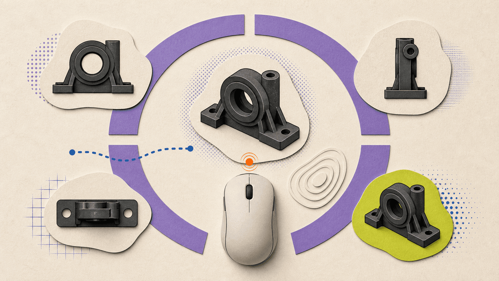
Mouse gestures can have 2, 3, 4, 8, or 12 directions. According to the current Mouse Gestures documentation, gestures are enabled by default and the guide initially displays four gestures.
The commands are configured separately for parts, assemblies, drawings, and sketches. This allows the same drag direction to open a sketch tool while sketching and a different feature or view tool while editing a part.
To modify them:
Open a SolidWorks document.
Go to Tools > Customize.
Select the Mouse Gestures tab.
Confirm that Enable mouse gestures is selected.
Choose the number of directions.
Drag commands into positions on the gesture guides.
Dragging a command into an occupied position replaces the existing command. Holding Ctrl while dragging between positions copies the command. The dialog also includes options for printing gesture guides and resetting them to factory defaults.
Mouse Gestures In Assemblies
Right-dragging directly on a component can rotate the component instead of opening the gesture wheel. To avoid that conflict, right-drag in blank graphics space.
If you need to begin over a component, use Alt + right-drag. This invokes mouse gestures instead of the Rotate Component behavior.
How Many Gestures Should You Use?
Four is a sensible starting point. The directions are easy to distinguish, and the guide remains readable. Move to eight or twelve only when the first set has become automatic and additional commands will remove meaningful repetition.
A recommended gesture arrangement is a customization, not a default. For example, one user might prioritize Normal To, Isometric, Measure, and Change Transparency. Another might need sketch relations, construction geometry, trim, and offset commands. The right setup depends on the work being performed.
What About Extra Mouse Buttons?
Current SOLIDWORKS Design Help documents the middle mouse button, wheel, right-drag gestures, and keyboard modifiers. It does not document a native interface for assigning commands directly to Mouse 4 or Mouse 5.
Extra side-button workflows therefore usually depend on the mouse manufacturer’s software. A per-application profile can make a side button send a verified keyboard shortcut, such as S, F, or a custom Measure key.
Treat that mapping as part of the mouse configuration, not as a default SolidWorks mouse button shortcut. The official Middle Mouse Button Functions page also warns that Windows or manufacturer settings can override expected wheel behavior.
Which View, Navigation, Selection, And Display Shortcuts Matter Most
View controls provide some of the largest daily time savings because rotating, zooming, and reorienting a model happen constantly.
View Orientation And Normal To
Press Spacebar to open the Orientation dialog. It provides standard views, saved views, View Selector access, and tools for updating standard orientations. The current Orientation Dialog Box documentation also explains how to create and preserve custom named views.
Use Ctrl + 7 when you want a quick Isometric view. Use Ctrl + 8 when you need to face a sketch, plane, planar face, or suitable feature directly.
Normal To is selection-sensitive:
Select a plane or planar face to view it directly.
Use it while editing a 2D sketch to align the model with the sketch.
Select a cylindrical or conical face to orient along its axis.
Select two nonparallel planar faces with
Ctrlto make the first face parallel to the screen and the second control the top direction.Invoke Normal To again to flip the view when supported.
The Viewing Models Normal To page describes these selection behaviors in more detail.
Middle-Mouse Navigation
For parts and assemblies:
Middle-drag rotates the model.
Ctrl + middle-dragpans.Shift + middle-dragzooms.Alt + middle-dragrolls the view parallel to the screen.Scrolling the wheel zooms around the pointer position.
In an active drawing, middle-drag pans because ordinary model rotation is not the expected sheet-navigation behavior.
If the wheel zooms in the opposite direction from what you expect, open Tools > Options > System Options > View and change the mouse-wheel zoom direction. If the behavior remains wrong, check the Windows mouse settings and the manufacturer’s application profile.
Hide And Show Geometry
Hover over a body or assembly component and press Tab to hide it. Hover over the hidden location and press Shift + Tab to show it again.
In an assembly, hold Ctrl + Shift + Tab to display hidden components temporarily as transparent. Click one of those components to change it back to shown, then release the keys.
This last workflow is assembly-specific. The visibility documentation states that it does not operate on child bodies inside those components.
Also remember that Tab and Shift + Tab have a different purpose while inserting an assembly component. In that context, they rotate the component by 90 degrees in opposite directions.
Transparency
Change Transparency is a useful command, but no universal factory keyboard shortcut should be assumed. The documented access routes include the component context toolbar, the Assembly toolbar, and the Display Pane.
If transparency is part of your everyday assembly workflow, add Change Transparency to the Assembly Shortcut Bar, assign it to a gesture, or create a keyboard shortcut. Label that key as your customization.
To select a transparent face instead of an opaque object behind it, hold Shift while selecting. The exact result also depends on Enable selection through transparency under Tools > Options > Selection. The Selection Through Transparency page explains both behaviors.
Selection Filters
If SolidWorks refuses to select the entity you expect, check the selection filters before assuming the mouse or model is broken.
Press F5 to show or hide the Selection Filter toolbar. Press F6 to toggle the configured filters. Current default filter keys include:
Efor edgesXfor facesVfor vertices
An active filter restricts what the pointer can select. This is useful when working in dense geometry, but confusing if the filter was activated accidentally.
Select Other is another valuable tool when several faces or edges overlap under the pointer. Current Help documents it in the right-click selection context toolbar and relevant shortcut menus, but not with a universal default keyboard shortcut. Add it to a shortcut interface if you use it frequently.
How To Speed Up Sketching, Measurement, Relations, And Features
Some of the most searched SolidWorks hotkeys do not have a universal factory key. Measurement, equations, Fix, Add Relation, Plane, Select Other, and Change Transparency are better treated as recommended customizations.
Sketch Relations
SolidWorks can add geometric relations automatically while you sketch. These include horizontal, vertical, coincident, tangent, and perpendicular relationships.
Hold Ctrl while creating sketch geometry to suppress automatic relations temporarily. This affects the current operation without permanently turning off Automatic Relations. To disable the feature more broadly, use Tools > Sketch Settings > Automatic Relations.
To add a relation after geometry has been created:
Select the relevant sketch entities.
Use the context toolbar, the Add Relations PropertyManager, or Tools > Relations > Add.
Choose a relation that is valid for the selection.
Fix is one of these relations. It constrains the size and location of suitable sketch geometry. It is not a general command for freezing any item in SolidWorks. The available relations always depend on what has been selected, as shown in the Geometric Relations documentation.
If you repeatedly add the same relations, place Add Relation or a specific relation in the Sketch Shortcut Bar. Do not describe the assigned key as a factory default.
Measurement And Inspection
Open the Measure tool from Tools > Evaluate > Measure or its toolbar button. It can report distances, angles, radii, coordinates, projected values, and other measurements supported by the selected geometry.
The tool works across sketches, 3D models, assemblies, and drawings. When it is not active, commonly used measurements for selected entities may also appear in the status bar.
There is no current universal Measure hotkey that should be promised to every reader. Assigning a memorable key, adding Measure to the S bar, or placing it on a mouse gesture is a good customization for inspection-heavy workflows. See Using the Measure Tool for its available measurement modes.
Equations
Open the Equations, Global Variables and Dimensions dialog through:
Tools > Equations
The Equations button on the Tools toolbar
Manage Equations from the Equations folder in the FeatureManager design tree
The command manages mathematical relationships, global variables, and dimension-driven logic in parts and assemblies. Current Help does not document a universal factory shortcut for opening it, so use the menu or create a personal binding. Accessing the Equations Dialog Box
Offset Planes
There is a useful modifier workflow for creating an offset copy of an existing plane:
Select the plane.
Hold
Ctrl.Drag the plane by its edge to a new location.
SolidWorks creates an offset plane. This is documented in Move, Resize, and Copy Planes.
It is a Ctrl plus mouse-drag workflow, not a standalone offset-plane keyboard shortcut. You can still assign the general Plane command to the S bar, a keyboard key, or a gesture.
Rebuild, Redraw, Undo, And Redo
Ctrl + B rebuilds changed features. Use it when model changes need to be recalculated.
Ctrl + R redraws the screen. It refreshes the visible display but does not perform the same model calculation as a rebuild.
Ctrl + Z undoes a supported recent action. Ctrl + Y redoes a supported undo. Redo availability depends on the operation and context, so it should not be described as a guarantee that every modeling action can be restored.
Press Enter to repeat the last supported command. This can be particularly helpful for repeated feature or sketch operations, provided a text box or active dialog is not capturing the key.
How To Customize And Save SolidWorks Shortcuts
Open a part, assembly, or drawing before customizing the interface. Then go to Tools > Customize > Keyboard.
The Keyboard tab provides:
A searchable command list
Existing shortcut assignments
Custom command-search terms
Conflict warnings
Shortcut removal
Reset to Defaults
Print List
Copy List
To assign a key:
Search for the command.
Select its Shortcut field.
Press the desired key or key combination.
Review any conflict warning.
Confirm the new assignment.
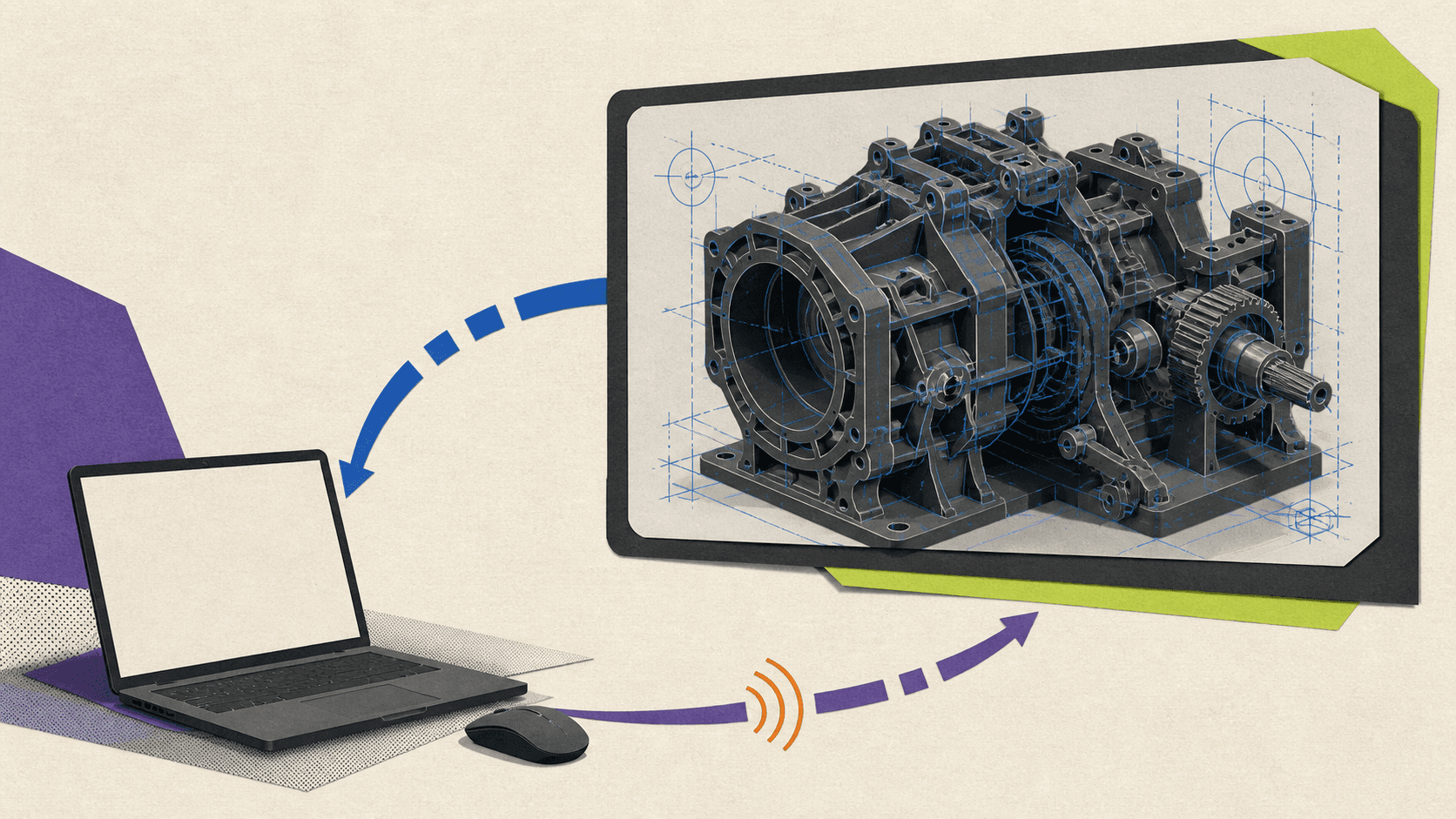
If the key is already assigned and you choose to reuse it, SolidWorks removes that key from the old command. This is a common reason a familiar shortcut suddenly stops working.
The current keyboard customization documentation also notes that ordinary keys can be interpreted as text while a text field has focus. Function keys are more reliable for commands that must work from inside a dialog, although you should still avoid replacing useful system defaults casually.
Build A Small Personal Hotkey Set
A practical custom set might include:
Measure
Equations
Add Relation
Fix
Plane
Select Other
Change Transparency
The exact keys are personal recommendations. Before assigning them, use Copy List to export the current mappings and check for conflicts.
Customize the three shortcut systems separately:
Use the Keyboard tab for direct key assignments.
Use the Shortcut Bars tab for mode-specific S key menus.
Use the Mouse Gestures tab for directional right-drag commands.
Save And Reuse Your Settings
Use Tools > Save/Restore Settings to open the SOLIDWORKS Settings Wizard. Depending on your selection, it can preserve:
Keyboard shortcuts
Mouse gestures
Menu customization
Toolbar layouts
System options
Saved views
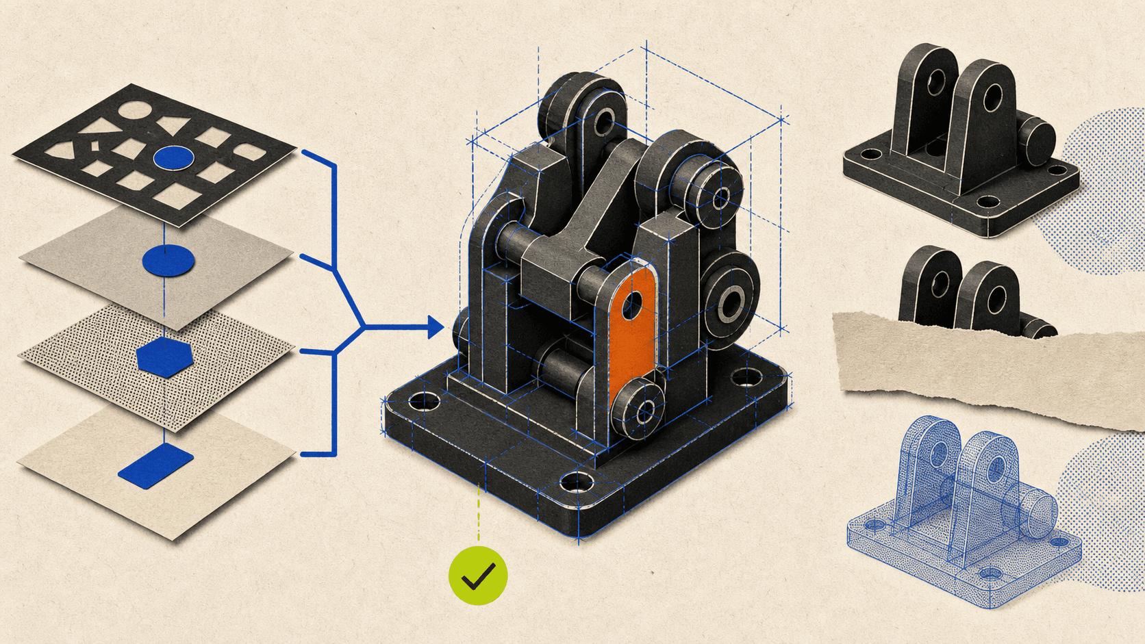
Settings are stored in a file that can be restored on another compatible workstation or used as a backup. The wizard is particularly useful before resetting the interface, reinstalling SolidWorks, moving to another computer, or testing someone else’s shortcut layout.
Back up the current settings before restoring a shared file. A restored profile can replace more than the keyboard map if the file contains additional interface or system options. The SOLIDWORKS Settings Wizard documentation lists the settings categories it can save.
A SolidWorks document template is not the same thing as a hotkey profile. Templates manage document-specific standards and properties. Keyboard and interface customizations belong to the user environment and should be transferred through the Settings Wizard.
For a closer look at workstation cards, gaming GPUs, certified drivers, and viewport requirements, see our guide to the best GPUs for SolidWorks.
Why A Shortcut Or Shortcut Box May Not Appear
If the S key Shortcut Bar, a context toolbar, or another shortcut does not appear, work through these checks in order.
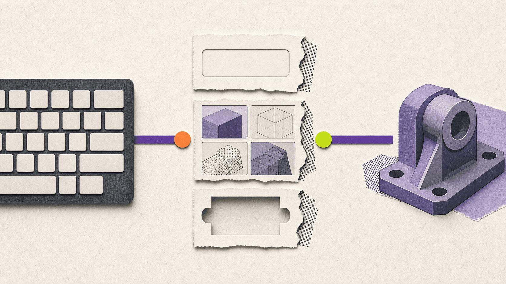
#1. Move Focus Out Of Text Fields
Click the graphics area and try the shortcut again. If a dimension field, search box, note, PropertyManager input, or other text field has focus, pressing S may type a letter instead of opening the Shortcut Bar.
#2. Confirm That A Document Is Open
Shortcut Bars are built around Part, Assembly, Drawing, and Sketch modes. Open the relevant document before testing or customizing the bar.
#3. Check The Active Mode
If Line is missing from the S bar, confirm that you are editing a sketch. If an assembly command is missing, confirm that an assembly is active. The four bars are customized independently.
Commands can also become unavailable when the current selection or document type does not support them.
#4. Verify The Assignment
Open Tools > Customize > Keyboard, search for Shortcut Bar, and check its assigned key. A custom profile may have changed or removed S.
Search for any missing direct command in the same dialog. It may now be assigned to a different key, or its previous key may have been transferred to another command after a conflict warning.
#5. Check Shortcut Bar Contents
Open Tools > Customize > Shortcut Bars and select the correct bar. Search for the missing command and drag it into place.
If the bar opens but command search is absent, check whether Show Command Search in the shortcut bars is enabled.
#6. Check Context Toolbar Settings
Go to Tools > Customize > Toolbars and review the context-toolbar options. Relevant settings include:
Show on selection
Show in shortcut menu
Show quick configurations
Show quick mates
A context toolbar cannot appear on selection if that visibility option is disabled.
#7. Check Mouse Gestures
Open Tools > Customize > Mouse Gestures and confirm that gestures are enabled. Right-drag in the graphics area rather than performing a normal right-click.
In an assembly, right-drag away from components or use Alt + right-drag. Otherwise, SolidWorks may interpret the action as component rotation.
#8. Check Mouse And Keyboard Software
Mouse-vendor utilities, keyboard managers, remote-desktop clients, accessibility tools, and Windows settings can intercept an input before SolidWorks receives it.
If middle-mouse navigation works incorrectly, inspect wheel configuration and application-specific mouse profiles. If only a side-button shortcut fails, verify that the mouse utility is sending the intended key to SolidWorks.
#9. Review Imported Settings
A restored .sldreg profile may have changed the keyboard map, gesture guide, toolbar layout, or menus. Restore your own backup when available.
Reset to Defaults is a valid final diagnostic step, but save the current settings first. Resetting can remove deliberate customizations along with the problematic one.
If shortcuts are only one symptom and SolidWorks is also freezing or closing unexpectedly, work through this SolidWorks crashing troubleshooting guide.
What About SolidWorks 2016, 2018, And 2019?
Older-version searches should be treated as troubleshooting context, not as evidence that every old shortcut differs.
For example, official SOLIDWORKS 2018 Help already documents S as the default Shortcut Bar key. Its mouse-gesture settings also included 2, 3, 4, 8, and 12 direction options.
Interfaces, labels, commands, add-ins, and local profiles can still differ. Use the Help version matching the installed release and inspect Tools > Customize > Keyboard for the actual assignment rather than relying on an unofficial SolidWorks keyboard shortcuts cheat sheet PDF.
When A Cloud Computer Helps With SolidWorks
Shortcuts remove interface friction. They do not make a slow rebuild, large assembly, or overloaded graphics pipeline calculate faster.
If performance remains the bottleneck, our guide to choosing the best PC for SolidWorks explains how CPU, memory, storage, and graphics hardware affect different CAD workloads.
SOLIDWORKS’ current system requirements recommend adequate memory, SSD storage, and certified graphics cards and drivers. Graphics performance also affects rotate, pan, zoom, shaded drawings, dynamic transparency, and other interactive display operations. The available controls are described under SOLIDWORKS Performance Options.
When complex parts, large assemblies, or heavy CAD files exceed a local laptop’s comfortable limits, Vagon Cloud Computer can provide remote access to a stronger Windows workstation with selectable CPU, RAM, and NVIDIA GPU performance.
That does not change how SolidWorks keyboard shortcuts work. It changes where SolidWorks performs the modeling, rebuild, and graphics work.
A remote CAD workflow has two performance considerations:
The cloud workstation must be powerful enough for the SolidWorks workload.
The connection must be responsive enough for interactive input.
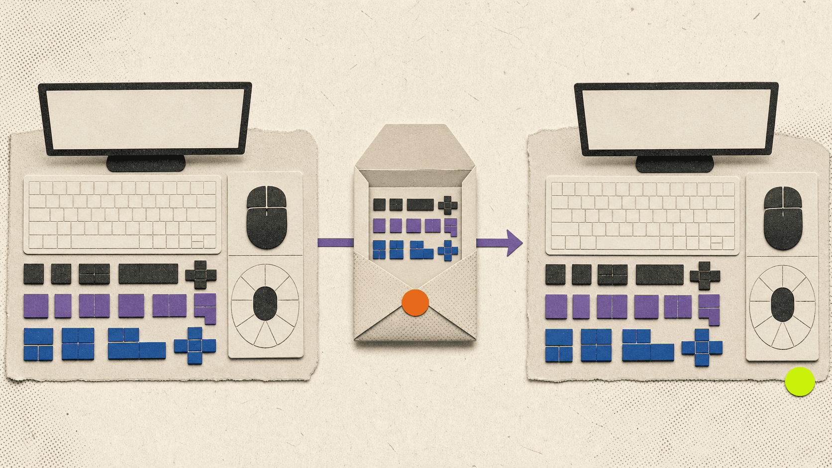
Network latency is particularly noticeable during mouse gestures, continuous view rotation, zooming, dragging sketch geometry, and selecting small entities. Use a nearby cloud region and a stable wired or strong Wi-Fi connection where possible. A powerful remote GPU cannot fully compensate for an unstable network path.
Your SolidWorks license, custom templates, mouse profiles, and user settings remain separate responsibilities. If you want the remote installation to feel familiar, export the local interface configuration with the SOLIDWORKS Settings Wizard and restore the appropriate settings inside the cloud workstation.
SolidWorks keyboard shortcuts are most effective when they form a small, dependable system. Learn the verified defaults first, keep the S key bar focused, add a few mouse gestures, and create custom hotkeys only for commands that genuinely interrupt your workflow.
If local hardware is the remaining bottleneck after the interface is optimized, try Vagon Cloud Computer to run your SolidWorks environment on a scalable remote workstation.
If your local device is a Mac, compare the available native, virtualized, and cloud-based options in our guide to running SolidWorks on macOS.
The most useful SolidWorks keyboard shortcuts are the ones that reduce repeated trips to menus: S for the Shortcut Bar, F for Zoom to Fit, Spacebar for View Orientation, Ctrl + 1 through Ctrl + 8 for standard views, and Tab controls for hiding or showing model geometry.
Start with those defaults, then customize only the commands you use frequently. SolidWorks shortcuts are highly configurable, so the shortcut on one workstation may not match another user’s setup. Document type, editing mode, keyboard focus, imported settings, and software version can also affect what appears.
The Most Useful SolidWorks Keyboard Shortcuts At A Glance
The following table focuses on high-value defaults documented by SOLIDWORKS. Some shortcuts are global, while others work only in a particular document type or editing context.
Action | Default Shortcut | Where It Works | Important Context |
|---|---|---|---|
Open the Shortcut Bar |
| Parts, assemblies, drawings, and sketches | Opens a different bar for each working mode |
Zoom to Fit |
| Parts, assemblies, and drawings | Fits visible content in the graphics area |
Zoom Out |
| Model and drawing views | Zooms out in fixed steps |
Zoom In |
| Model and drawing views | Zooms in in fixed steps |
Open View Orientation |
| Primarily parts and assemblies | Opens the View Selector and Orientation dialog |
Open the View Selector |
| Model-viewing contexts | Opens the selector without the full Orientation dialog |
Front View |
| Model orientation | Changes to Front |
Back View |
| Model orientation | Changes to Back |
Left View |
| Model orientation | Changes to Left |
Right View |
| Model orientation | Changes to Right |
Top View |
| Model orientation | Changes to Top |
Bottom View |
| Model orientation | Changes to Bottom |
Isometric View |
| Model orientation | Changes to Isometric |
Normal To |
| Sketches, planes, faces, and suitable selected geometry | Selection determines the resulting orientation |
Hide Hovered Item |
| Bodies and assembly components | During component insertion, it rotates the component instead |
Show Hovered Hidden Item |
| Bodies and assembly components | Also has a different meaning during component insertion |
Temporarily Reveal Hidden Components | Hold | Assemblies | Click a transparent hidden component to show it |
Rebuild |
| Model documents | Rebuilds changed features |
Redraw |
| Active document | Refreshes the display, but does not rebuild the model |
Repeat Last Command |
| Supported command contexts | A dialog or text field may capture the key |
Undo |
| Most editing workflows | Reverses a supported recent action |
Redo |
| Supported undo workflows | Not every operation can be redone |
Select Multiple Items |
| Graphics area and FeatureManager tree | Active selection filters still apply |
Select All |
| Parts, assemblies, and drawings | What is selected depends on document type and filters |
Show Selection Filter Toolbar |
| Selection workflows | Helps restrict selection to specific geometry types |
Toggle Active Selection Filters |
| Selection workflows | Turns configured filters on or off |
Open Shortcut Menu |
| Contexts with a shortcut menu | Keyboard alternative to right-clicking |
These controls are documented across the current Selected Keyboard Shortcuts, Shortcut Bars, and Selection Filter Toolbar help pages. The standard numeric view mappings are also documented in an official SOLIDWORKS view-navigation reference.
Treat the table as a starting point, not proof of what is currently assigned on your computer. A company profile, settings restore, previous customization, or another user can change the mappings. To inspect your actual SolidWorks hotkeys, open a document and go to Tools > Customize > Keyboard.
How The S Key, Shortcut Bar, And Command Search Work
The S key opens the Shortcut Bar next to the pointer. This is one of the most useful SolidWorks shortcuts because it provides quick access to multiple commands without requiring a separate hotkey for every tool.
SolidWorks maintains different Shortcut Bars for:
Parts
Assemblies
Drawings
Sketches
This is why pressing S while editing a sketch does not show the same commands you see while working on a completed part. The application displays the bar associated with the active working mode.
The Shortcut Bar is sometimes described as context-sensitive, but there is an important nuance. Its command set changes with the working mode, not with every individual object you select. A right-click shortcut menu or context toolbar is more directly driven by the selected face, edge, sketch entity, feature, or component.
For example, if you want rapid access to the Line tool:
Enter or edit a sketch.
Press
S.Select Line from the Sketch Shortcut Bar.
If Line is missing, customize the Sketch bar and add it.
Do not interpret this workflow as an S + L keyboard combination. The S key opens the bar. Line is then chosen from that bar unless you have separately assigned a direct key to the Line command.
Current Shortcut Bars can also include Search All Commands. Start typing the name of a tool, select it in the results, and either run it or insert it into the Shortcut Bar. The general Search Commands feature also shows assigned keyboard shortcuts in its results.
You can operate the bar without immediately returning to the mouse:
Use the arrow keys to move between tools.
Press
Alt + Down Arrowto open a selected tool’s menu, when available.Press
Enterto run the selected tool.Press
Escto dismiss the bar.
To customize a Shortcut Bar, open a document and select Tools > Customize > Shortcut Bars. Choose the Part, Assembly, Drawing, or Sketch bar, then drag commands onto it. You can also press S, right-click the open bar, and select Customize when nothing is selected in the graphics area.
A practical setup is to reserve direct keyboard shortcuts for a small group of universal actions and use the S key for commands that are important but strongly tied to a particular modeling mode.
How SolidWorks Mouse Gestures And Extra Mouse Buttons Work
SolidWorks mouse gestures are separate from keyboard shortcuts and the S key. They let you execute a mapped command by right-dragging in a direction.
To use a gesture:
Right-drag in the graphics area.
Continue dragging toward the command shown in the gesture guide.
Move through the command region.
Release the button to execute it.
Release the button inside the center of the guide if you want to cancel.
Mouse gestures can have 2, 3, 4, 8, or 12 directions. According to the current Mouse Gestures documentation, gestures are enabled by default and the guide initially displays four gestures.
The commands are configured separately for parts, assemblies, drawings, and sketches. This allows the same drag direction to open a sketch tool while sketching and a different feature or view tool while editing a part.
To modify them:
Open a SolidWorks document.
Go to Tools > Customize.
Select the Mouse Gestures tab.
Confirm that Enable mouse gestures is selected.
Choose the number of directions.
Drag commands into positions on the gesture guides.
Dragging a command into an occupied position replaces the existing command. Holding Ctrl while dragging between positions copies the command. The dialog also includes options for printing gesture guides and resetting them to factory defaults.
Mouse Gestures In Assemblies
Right-dragging directly on a component can rotate the component instead of opening the gesture wheel. To avoid that conflict, right-drag in blank graphics space.
If you need to begin over a component, use Alt + right-drag. This invokes mouse gestures instead of the Rotate Component behavior.
How Many Gestures Should You Use?
Four is a sensible starting point. The directions are easy to distinguish, and the guide remains readable. Move to eight or twelve only when the first set has become automatic and additional commands will remove meaningful repetition.
A recommended gesture arrangement is a customization, not a default. For example, one user might prioritize Normal To, Isometric, Measure, and Change Transparency. Another might need sketch relations, construction geometry, trim, and offset commands. The right setup depends on the work being performed.
What About Extra Mouse Buttons?
Current SOLIDWORKS Design Help documents the middle mouse button, wheel, right-drag gestures, and keyboard modifiers. It does not document a native interface for assigning commands directly to Mouse 4 or Mouse 5.
Extra side-button workflows therefore usually depend on the mouse manufacturer’s software. A per-application profile can make a side button send a verified keyboard shortcut, such as S, F, or a custom Measure key.
Treat that mapping as part of the mouse configuration, not as a default SolidWorks mouse button shortcut. The official Middle Mouse Button Functions page also warns that Windows or manufacturer settings can override expected wheel behavior.
Which View, Navigation, Selection, And Display Shortcuts Matter Most
View controls provide some of the largest daily time savings because rotating, zooming, and reorienting a model happen constantly.
View Orientation And Normal To
Press Spacebar to open the Orientation dialog. It provides standard views, saved views, View Selector access, and tools for updating standard orientations. The current Orientation Dialog Box documentation also explains how to create and preserve custom named views.
Use Ctrl + 7 when you want a quick Isometric view. Use Ctrl + 8 when you need to face a sketch, plane, planar face, or suitable feature directly.
Normal To is selection-sensitive:
Select a plane or planar face to view it directly.
Use it while editing a 2D sketch to align the model with the sketch.
Select a cylindrical or conical face to orient along its axis.
Select two nonparallel planar faces with
Ctrlto make the first face parallel to the screen and the second control the top direction.Invoke Normal To again to flip the view when supported.
The Viewing Models Normal To page describes these selection behaviors in more detail.
Middle-Mouse Navigation
For parts and assemblies:
Middle-drag rotates the model.
Ctrl + middle-dragpans.Shift + middle-dragzooms.Alt + middle-dragrolls the view parallel to the screen.Scrolling the wheel zooms around the pointer position.
In an active drawing, middle-drag pans because ordinary model rotation is not the expected sheet-navigation behavior.
If the wheel zooms in the opposite direction from what you expect, open Tools > Options > System Options > View and change the mouse-wheel zoom direction. If the behavior remains wrong, check the Windows mouse settings and the manufacturer’s application profile.
Hide And Show Geometry
Hover over a body or assembly component and press Tab to hide it. Hover over the hidden location and press Shift + Tab to show it again.
In an assembly, hold Ctrl + Shift + Tab to display hidden components temporarily as transparent. Click one of those components to change it back to shown, then release the keys.
This last workflow is assembly-specific. The visibility documentation states that it does not operate on child bodies inside those components.
Also remember that Tab and Shift + Tab have a different purpose while inserting an assembly component. In that context, they rotate the component by 90 degrees in opposite directions.
Transparency
Change Transparency is a useful command, but no universal factory keyboard shortcut should be assumed. The documented access routes include the component context toolbar, the Assembly toolbar, and the Display Pane.
If transparency is part of your everyday assembly workflow, add Change Transparency to the Assembly Shortcut Bar, assign it to a gesture, or create a keyboard shortcut. Label that key as your customization.
To select a transparent face instead of an opaque object behind it, hold Shift while selecting. The exact result also depends on Enable selection through transparency under Tools > Options > Selection. The Selection Through Transparency page explains both behaviors.
Selection Filters
If SolidWorks refuses to select the entity you expect, check the selection filters before assuming the mouse or model is broken.
Press F5 to show or hide the Selection Filter toolbar. Press F6 to toggle the configured filters. Current default filter keys include:
Efor edgesXfor facesVfor vertices
An active filter restricts what the pointer can select. This is useful when working in dense geometry, but confusing if the filter was activated accidentally.
Select Other is another valuable tool when several faces or edges overlap under the pointer. Current Help documents it in the right-click selection context toolbar and relevant shortcut menus, but not with a universal default keyboard shortcut. Add it to a shortcut interface if you use it frequently.
How To Speed Up Sketching, Measurement, Relations, And Features
Some of the most searched SolidWorks hotkeys do not have a universal factory key. Measurement, equations, Fix, Add Relation, Plane, Select Other, and Change Transparency are better treated as recommended customizations.
Sketch Relations
SolidWorks can add geometric relations automatically while you sketch. These include horizontal, vertical, coincident, tangent, and perpendicular relationships.
Hold Ctrl while creating sketch geometry to suppress automatic relations temporarily. This affects the current operation without permanently turning off Automatic Relations. To disable the feature more broadly, use Tools > Sketch Settings > Automatic Relations.
To add a relation after geometry has been created:
Select the relevant sketch entities.
Use the context toolbar, the Add Relations PropertyManager, or Tools > Relations > Add.
Choose a relation that is valid for the selection.
Fix is one of these relations. It constrains the size and location of suitable sketch geometry. It is not a general command for freezing any item in SolidWorks. The available relations always depend on what has been selected, as shown in the Geometric Relations documentation.
If you repeatedly add the same relations, place Add Relation or a specific relation in the Sketch Shortcut Bar. Do not describe the assigned key as a factory default.
Measurement And Inspection
Open the Measure tool from Tools > Evaluate > Measure or its toolbar button. It can report distances, angles, radii, coordinates, projected values, and other measurements supported by the selected geometry.
The tool works across sketches, 3D models, assemblies, and drawings. When it is not active, commonly used measurements for selected entities may also appear in the status bar.
There is no current universal Measure hotkey that should be promised to every reader. Assigning a memorable key, adding Measure to the S bar, or placing it on a mouse gesture is a good customization for inspection-heavy workflows. See Using the Measure Tool for its available measurement modes.
Equations
Open the Equations, Global Variables and Dimensions dialog through:
Tools > Equations
The Equations button on the Tools toolbar
Manage Equations from the Equations folder in the FeatureManager design tree
The command manages mathematical relationships, global variables, and dimension-driven logic in parts and assemblies. Current Help does not document a universal factory shortcut for opening it, so use the menu or create a personal binding. Accessing the Equations Dialog Box
Offset Planes
There is a useful modifier workflow for creating an offset copy of an existing plane:
Select the plane.
Hold
Ctrl.Drag the plane by its edge to a new location.
SolidWorks creates an offset plane. This is documented in Move, Resize, and Copy Planes.
It is a Ctrl plus mouse-drag workflow, not a standalone offset-plane keyboard shortcut. You can still assign the general Plane command to the S bar, a keyboard key, or a gesture.
Rebuild, Redraw, Undo, And Redo
Ctrl + B rebuilds changed features. Use it when model changes need to be recalculated.
Ctrl + R redraws the screen. It refreshes the visible display but does not perform the same model calculation as a rebuild.
Ctrl + Z undoes a supported recent action. Ctrl + Y redoes a supported undo. Redo availability depends on the operation and context, so it should not be described as a guarantee that every modeling action can be restored.
Press Enter to repeat the last supported command. This can be particularly helpful for repeated feature or sketch operations, provided a text box or active dialog is not capturing the key.
How To Customize And Save SolidWorks Shortcuts
Open a part, assembly, or drawing before customizing the interface. Then go to Tools > Customize > Keyboard.
The Keyboard tab provides:
A searchable command list
Existing shortcut assignments
Custom command-search terms
Conflict warnings
Shortcut removal
Reset to Defaults
Print List
Copy List
To assign a key:
Search for the command.
Select its Shortcut field.
Press the desired key or key combination.
Review any conflict warning.
Confirm the new assignment.
If the key is already assigned and you choose to reuse it, SolidWorks removes that key from the old command. This is a common reason a familiar shortcut suddenly stops working.
The current keyboard customization documentation also notes that ordinary keys can be interpreted as text while a text field has focus. Function keys are more reliable for commands that must work from inside a dialog, although you should still avoid replacing useful system defaults casually.
Build A Small Personal Hotkey Set
A practical custom set might include:
Measure
Equations
Add Relation
Fix
Plane
Select Other
Change Transparency
The exact keys are personal recommendations. Before assigning them, use Copy List to export the current mappings and check for conflicts.
Customize the three shortcut systems separately:
Use the Keyboard tab for direct key assignments.
Use the Shortcut Bars tab for mode-specific S key menus.
Use the Mouse Gestures tab for directional right-drag commands.
Save And Reuse Your Settings
Use Tools > Save/Restore Settings to open the SOLIDWORKS Settings Wizard. Depending on your selection, it can preserve:
Keyboard shortcuts
Mouse gestures
Menu customization
Toolbar layouts
System options
Saved views
Settings are stored in a file that can be restored on another compatible workstation or used as a backup. The wizard is particularly useful before resetting the interface, reinstalling SolidWorks, moving to another computer, or testing someone else’s shortcut layout.
Back up the current settings before restoring a shared file. A restored profile can replace more than the keyboard map if the file contains additional interface or system options. The SOLIDWORKS Settings Wizard documentation lists the settings categories it can save.
A SolidWorks document template is not the same thing as a hotkey profile. Templates manage document-specific standards and properties. Keyboard and interface customizations belong to the user environment and should be transferred through the Settings Wizard.
For a closer look at workstation cards, gaming GPUs, certified drivers, and viewport requirements, see our guide to the best GPUs for SolidWorks.
Why A Shortcut Or Shortcut Box May Not Appear
If the S key Shortcut Bar, a context toolbar, or another shortcut does not appear, work through these checks in order.
#1. Move Focus Out Of Text Fields
Click the graphics area and try the shortcut again. If a dimension field, search box, note, PropertyManager input, or other text field has focus, pressing S may type a letter instead of opening the Shortcut Bar.
#2. Confirm That A Document Is Open
Shortcut Bars are built around Part, Assembly, Drawing, and Sketch modes. Open the relevant document before testing or customizing the bar.
#3. Check The Active Mode
If Line is missing from the S bar, confirm that you are editing a sketch. If an assembly command is missing, confirm that an assembly is active. The four bars are customized independently.
Commands can also become unavailable when the current selection or document type does not support them.
#4. Verify The Assignment
Open Tools > Customize > Keyboard, search for Shortcut Bar, and check its assigned key. A custom profile may have changed or removed S.
Search for any missing direct command in the same dialog. It may now be assigned to a different key, or its previous key may have been transferred to another command after a conflict warning.
#5. Check Shortcut Bar Contents
Open Tools > Customize > Shortcut Bars and select the correct bar. Search for the missing command and drag it into place.
If the bar opens but command search is absent, check whether Show Command Search in the shortcut bars is enabled.
#6. Check Context Toolbar Settings
Go to Tools > Customize > Toolbars and review the context-toolbar options. Relevant settings include:
Show on selection
Show in shortcut menu
Show quick configurations
Show quick mates
A context toolbar cannot appear on selection if that visibility option is disabled.
#7. Check Mouse Gestures
Open Tools > Customize > Mouse Gestures and confirm that gestures are enabled. Right-drag in the graphics area rather than performing a normal right-click.
In an assembly, right-drag away from components or use Alt + right-drag. Otherwise, SolidWorks may interpret the action as component rotation.
#8. Check Mouse And Keyboard Software
Mouse-vendor utilities, keyboard managers, remote-desktop clients, accessibility tools, and Windows settings can intercept an input before SolidWorks receives it.
If middle-mouse navigation works incorrectly, inspect wheel configuration and application-specific mouse profiles. If only a side-button shortcut fails, verify that the mouse utility is sending the intended key to SolidWorks.
#9. Review Imported Settings
A restored .sldreg profile may have changed the keyboard map, gesture guide, toolbar layout, or menus. Restore your own backup when available.
Reset to Defaults is a valid final diagnostic step, but save the current settings first. Resetting can remove deliberate customizations along with the problematic one.
If shortcuts are only one symptom and SolidWorks is also freezing or closing unexpectedly, work through this SolidWorks crashing troubleshooting guide.
What About SolidWorks 2016, 2018, And 2019?
Older-version searches should be treated as troubleshooting context, not as evidence that every old shortcut differs.
For example, official SOLIDWORKS 2018 Help already documents S as the default Shortcut Bar key. Its mouse-gesture settings also included 2, 3, 4, 8, and 12 direction options.
Interfaces, labels, commands, add-ins, and local profiles can still differ. Use the Help version matching the installed release and inspect Tools > Customize > Keyboard for the actual assignment rather than relying on an unofficial SolidWorks keyboard shortcuts cheat sheet PDF.
When A Cloud Computer Helps With SolidWorks
Shortcuts remove interface friction. They do not make a slow rebuild, large assembly, or overloaded graphics pipeline calculate faster.
If performance remains the bottleneck, our guide to choosing the best PC for SolidWorks explains how CPU, memory, storage, and graphics hardware affect different CAD workloads.
SOLIDWORKS’ current system requirements recommend adequate memory, SSD storage, and certified graphics cards and drivers. Graphics performance also affects rotate, pan, zoom, shaded drawings, dynamic transparency, and other interactive display operations. The available controls are described under SOLIDWORKS Performance Options.
When complex parts, large assemblies, or heavy CAD files exceed a local laptop’s comfortable limits, Vagon Cloud Computer can provide remote access to a stronger Windows workstation with selectable CPU, RAM, and NVIDIA GPU performance.
That does not change how SolidWorks keyboard shortcuts work. It changes where SolidWorks performs the modeling, rebuild, and graphics work.
A remote CAD workflow has two performance considerations:
The cloud workstation must be powerful enough for the SolidWorks workload.
The connection must be responsive enough for interactive input.
Network latency is particularly noticeable during mouse gestures, continuous view rotation, zooming, dragging sketch geometry, and selecting small entities. Use a nearby cloud region and a stable wired or strong Wi-Fi connection where possible. A powerful remote GPU cannot fully compensate for an unstable network path.
Your SolidWorks license, custom templates, mouse profiles, and user settings remain separate responsibilities. If you want the remote installation to feel familiar, export the local interface configuration with the SOLIDWORKS Settings Wizard and restore the appropriate settings inside the cloud workstation.
SolidWorks keyboard shortcuts are most effective when they form a small, dependable system. Learn the verified defaults first, keep the S key bar focused, add a few mouse gestures, and create custom hotkeys only for commands that genuinely interrupt your workflow.
If local hardware is the remaining bottleneck after the interface is optimized, try Vagon Cloud Computer to run your SolidWorks environment on a scalable remote workstation.
If your local device is a Mac, compare the available native, virtualized, and cloud-based options in our guide to running SolidWorks on macOS.
Get Beyond Your Computer Performance
Run applications on your cloud computer with the latest generation hardware. No more crashes or lags.

Trial includes 1 hour usage + 7 days of storage.
Summarize with AI
Ready to focus on your creativity?
Vagon gives you the ability to create & render projects, collaborate, and stream applications with the power of the best hardware.
Vagon Blog
Run heavy applications on any device with
your personal computer on the cloud.
San Francisco, California
Solutions
Vagon Teams
Vagon Streams
Use Cases
Resources
Vagon Blog
How to Use DaVinci Resolve With Codex: MCP & Computer Use
How to Use ComfyUI With Claude: MCP & Computer Use Guide
How to Use Rhino With Codex: MCP & Computer Use Guide
How to Use KiCad With Codex: MCP & Computer Use Guide
How to Use KiCad With Claude: MCP & Computer Use Guide Meta
How to Use FreeCAD With Codex: MCP & Computer Use
How to Use FreeCAD With Claude: MCP & Computer Use
How to Use 3ds Max With Codex: MCP & Computer Use
How to Use Houdini With Claude: MCP & Computer Use
Vagon Blog
Run heavy applications on any device with
your personal computer on the cloud.
San Francisco, California
Solutions
Vagon Teams
Vagon Streams
Use Cases
Resources
Vagon Blog
How to Use DaVinci Resolve With Codex: MCP & Computer Use
How to Use ComfyUI With Claude: MCP & Computer Use Guide
How to Use Rhino With Codex: MCP & Computer Use Guide
How to Use KiCad With Codex: MCP & Computer Use Guide
How to Use KiCad With Claude: MCP & Computer Use Guide Meta
How to Use FreeCAD With Codex: MCP & Computer Use
How to Use FreeCAD With Claude: MCP & Computer Use
How to Use 3ds Max With Codex: MCP & Computer Use
How to Use Houdini With Claude: MCP & Computer Use
Vagon Blog
Run heavy applications on any device with
your personal computer on the cloud.
San Francisco, California
Solutions
Vagon Teams
Vagon Streams
Use Cases
Resources
Vagon Blog